 Ciro Santilli
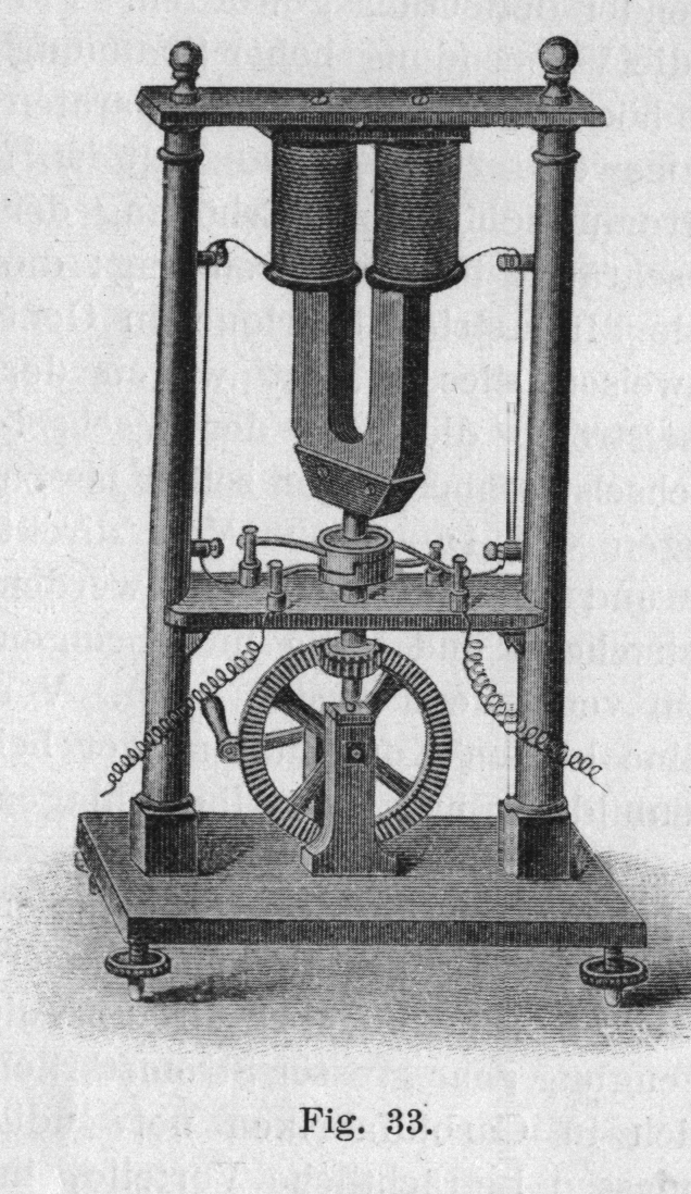
 Operated by a hand crank.
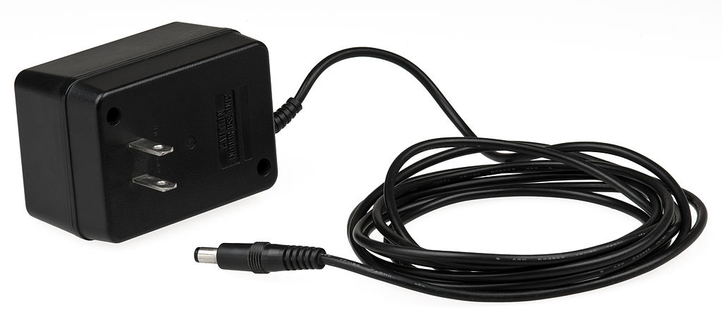
Positive center is way more popular: gearspace.com/board/electronic-music-instruments-and-electronic-music-production/1222518-center-negative-vs-center-positive-power-supply.html


This notation is designed to be relatively easy to write. This is achieved by not drawing ultra complex ASCII art boxes of every component. It would be slightly more readable if we did that, but prioritizing the writer here.
Two wires are only joined if
but the following are:
+ is given. E.g. the following two wires are not joined:
  |
--|--
| |
--+--
|Simple symmetric components:
-,+and|: wireAC: AC source. Parameters:e.g.:Hz: frequencyV: peak voltage
If only one side is given, the other is assumed to be at a groundAC_1Hz_2VG.C: capacitorG: ground. Often used together withDC, e.g.:means applying a voltage of 10 V across a 10 Ohm resistor, which would lead to a current of 1 ADC_10---R_10---GL: inductorMICROPHONE. As a multi-letter symmetric component, you can connect the two wires anywhere, e.g.or:---MICROPHONE---| MICROPHONE |SPEAKERR: resistorSQUID: SQUID deviceX: Josephson junction
Asymmetric components have multiple letters indicating different ports. The capital letter indicates the device, and lower case letters the ports. The wires then go into the ports:
D: diodeSample usage in a circuit:a: anode (where electrons can come in from)c: cathode
Can also be used vertically like aany other circuit:--aDc--We can also change the port order, the device is still the same due to capital| a D c |D:--cDa-- | Dac-- | Dca-- | --caDDCDC source. Ports:E.g. a 10 V source with a 10 Ohm resistor would be:p: positiven: negative
If only one side is given, the other is assumed to be at a the ground+---pDC_10_n---+ | | +----R_10------+G. We can also omitpandmin that case and assume thatpis the one used, e.g. the above would be equivalent to:If the voltage is not given, it is assumed to be a potentiometer.DC_10---R_10---GT: transistor. The ports aresgTd:Sample usage in a circuit:s: sourceg: gated: gate
All the following are also equivalent:---+ | --sgTd--| g --sTd-- | --Tsgd-- |I: electric current source. Ports:s: electron sourced: electron destination
V: Voltmeter. Ports:If we don't need to specify explicit positive and negative sides, we can just use:p: positiven: negative
without any ports. This is notably often the case for AC circuits.---V---Optionaly, we can also add the sides as in:
Numbers characterizing components are put just next to each component with an underscore. When there is only one parameter, standard units are assumed, e.g.:
means:Micro is denoted as
+-----+
|     |
C_1p  R_2k
|     |
+-----+- a capacitor with 1 pico Faraday
- a resistor with 2 k Ohms
u.Wires can just freely come in and out of specs of a component, they are then just connected to the component, e.g.:
means applying a voltage of 10 V across a 10 Ohm resistor, which would lead to a current of 1 A
DC_10---R_10---GIf a component has more than two parameters, units are used to distinguish them when possible, e.g.:
means an AC source with:
AC_1kV_2MHz- 1 kV voltage
- 1 MHz frequency
Main implementations: the same as electronic switches: vacuum tubes in the past, and transistors in the second half of the 20th century.
The fundamental intuition about capacitors is that they never let electrons through.
They can only absorb electrons up to a certain point, but then the pushback becomes too strong, and current stops.
Therefore, they cannot conduct direct current long term.
For alternating current however, things are different, because in alternating current, electrons are just jiggling back and forward a little bit around a center point. So you can send alternating current power across a capacitor.
The key equation that relates Voltage to electric current in the capacitor is:
So if a voltage Heavyside step function is applied what happens is:More realistically, one may consider the behaviour or the series RC circuit to see what happens without infinities when a capacitor is involved as in the step response of the series RC circuit.
- the capacitor fills up instantly with an infinite current
- the current then stops instantly


Ideally can be thought of as a one-way ticket gate that only lets electrons go in one direction with zero resistance! Real devices do have imperfections however, so there is some resistance.
First they were made out of vacuum tubes, but later semiconductor diodes were invented and became much more widespread.

- youtu.be/Fwj_d3uO5g8?t=153 how it works
- youtu.be/Fwj_d3uO5g8?t=514 applications:
- protection against accidental battery inversion
- rectifiers, notably mentions a diode bridge
GPIO generally only supports discrete outputs.
But for some types of hardware, like LEDs and some motors, the system has some inertia, and if you switch on and off fast enough, you get a result similar to having an intermediate voltage.
So with pulse width modulation we can fake analog output from digital output in a good enough manner.
Notably used to connect:
- pin headers
- breadboard holes
You can buy large sets of them in combitation of male/male, male/female, female/female. Male/male is perhaps the most important
These often come pre-soldered on devboards, e.g. and allow for easy access to GPIO pins. E.g. they're present on the Raspberry Pi 2.
Why would someone ever sell a devboard without them pre-soldered!


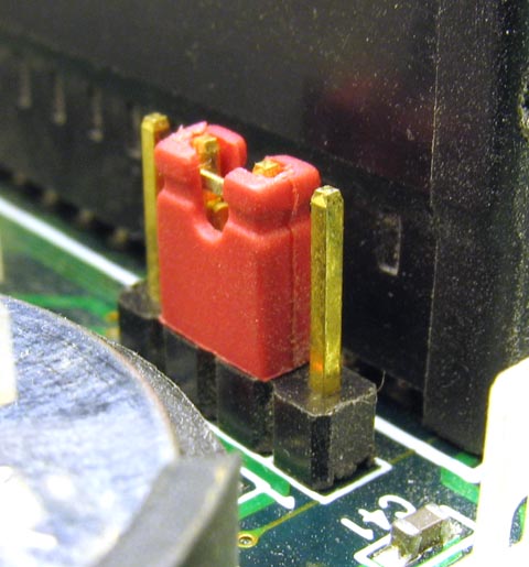
Allows you to connect two adjacent pins of a pin header. Sometimes used as a hardware configuration interface!
Something where DC voltage comes in, and a periodic voltage comes out.
- youtu.be/eYVOdlK15Og?t=66 RC oscillator on breadboard. Produces rectangular wave. Mentions popular integrated circuit that does it: 555 timer IC.
- youtu.be/eYVOdlK15Og?t=175 LC oscillators allows for higher frequencies. Produces sinusoidal output on MHz range. Uses an amplifier to feed back into input and maintain same voltage. Hard to make reliably on breadboard.
- youtu.be/eYVOdlK15Og?t=315 crystal oscillator. Mentions it acts like an LC oscillators. Shows and equivalent model. Wish he had talked more about them. You need support components around it: similarly to the LC case, the amplifier is generally not packaged in.
Oscillator made of an LC circuit.
It resists to change in electric current. Well seen at: Video "LC circuit by Eugene Khutoryansky (2016)".
Although transistors were revolutionary, it is fun to note that they were just "way cheaper and more reliable and smaller" versions of exactly the main functions that a vacuum tube could achieve
People had already patented a lot of stuff before without being able to make them work. Nonsense.
As the name suggests, this is not very sturdy, and was quickly replaced by bipolar junction transistor.
By William Shockley in 1948 also at Bell Labs Murray Hill.
As of 2020, not used anymore in logic gates, but still used in amplifiers.


By Andy Haas, an experimental particle physics professor: as.nyu.edu/content/nyu-as/as/faculty/andy-haas.html What an awesome dude!
899 USD as of 2022, takes a year to ship as they gather up a lot of orders before producing.
Sounds so cool, especially the multi functionality. Shame so expensive.
They do seem to have been very innovative, and have had a very good work culture. They also had a huge impact on the Silicon Valley startup scene.
Some products they are known for:
- oscilloscopes
- Atomic clocks, notably highly portable ones, see e.g. Video "Inside the HP 5061A Cesium Clock by CuriousMarc (2020)"
- pocket calculator
In a way, Agilent represents the most grassroots electronics parts of HP from before they became overly invested in laptops and fell.
They spun out the electronics part as Keysight in 2014, becoming life science only.
This is the cutest product name ever.
Since 1992, Mr. SQUID has been the standard educational demonstration system for undergraduate physics lab courses.
YBCO device, runs on liquid nitrogen.
This is how electronic circuits are normally prototyped!
Once you validate them like this, the next step is usually to move on to printed circuit boards for more reliable production setups.
Breadboards are a thing of beauty and wonder.

Bluetooth support: not enough RAM for it, though in principle its chip/transceiver could support it! microbit-micropython.readthedocs.io/en/v1.0.1/ble.html
Supported editors: microbit.org/code/
MicroPython web editor and compiler: python.microbit.org/v/2
Everything in this section is tested on the Micro Bit v1 from Micro Bit v1 unless otherwise noted.
Bibliography:

Microbit simulator using some Microsoft framework.
TODO the Python code from there does not seem to run on the microbit via
uflash, because it is not MicroPython.support.microbit.org/support/solutions/articles/19000111744-makecode-python-and-micropython explains.
forum.makecode.com/t/help-understanding-local-build-options/6130 asks how to compile locally and suggests it is possible. Seems to require Yotta, so presumably compiles?
Presumably this is because Microsoft ported their MakeCode thing to the MicroBit, and the Micro Bit foundation accepted them.
E.g. there toggling a LED:
but the code that works locally is a completely differently named API
Microsoft going all in on adopt extend extinguish from an early age!
led.toggle(0, 0)set_pixel:
microbit.display.set_pixel(0, 0, )When plugged into Ubuntu 22.04 via the USB Micro-B the Micro Bit mounts as:
e.g.:
for username
/media/$USER/MICROBIT//media/ciro/MICROBIT/ciro.Loading the program is done by simply copying a
The file name does not matter, only the
.hex binary into the image e.g. with:
cp ~/Downloads/microbit_program.hex /media/$USER/MICROBIT/.hex extension.The back power light flashes while upload is happening.
Flashing takes about 10-15 seconds for the 1.8 MB scroll display hello world from microbit-micropython.readthedocs.io/en/v1.0.1/tutorials/hello.html:
and the program starts executing immediately after flash ends.
from microbit import *
display.scroll("Hello, World!")You can restart the program by clicking the reset button near the USB. When you push down the program dies, and it restarts as soon as you release the button.
To use a prebuilt firmware, you can just use
What that does is:
uflash, tested on Ubuntu 22.04:
git clone https://github.com/bbcmicrobit/micropython
cd micropython
git checkout 7fc33d13b31a915cbe90dc5d515c6337b5fa1660
uflash examples/led_dance.py- convert the MicroPython code to bytecode
- join it up with a prebuilt firmware that ships with uflash which contains the MicroPython interpreter
- flashes that
To build your own firmware see:
Got it working: Compile MicroPython code for Micro Bit locally on Ubuntu 22.04 with your own firmware
TODO didn't manage from source Ubuntu 22.04, their setup bitrotted way too fast... it's shameful even. Until I gave up and went for the magic Docker of + github.com/bbcmicrobit/micropython, and it bloody worked:
git clone https://github.com/bbcmicrobit/micropython
cd micropython
git checkout 7fc33d13b31a915cbe90dc5d515c6337b5fa1660
docker pull ghcr.io/carlosperate/microbit-toolchain:latest
docker run -v $(pwd):/home --rm ghcr.io/carlosperate/microbit-toolchain:latest yt target bbc-microbit-classic-gcc-nosd@https://github.com/lancaster-university/yotta-target-bbc-microbit-classic-gcc-nosd
docker run -v $(pwd):/home --rm ghcr.io/carlosperate/microbit-toolchain:latest make all

# Build one.
tools/makecombinedhex.py build/firmware.hex examples/counter.py -o build/counter.hex
cp build/counter.hex "/media/$USER/MICROBIT/"

# Build all.
for f in examples/*; do b="$(basename "$f")"; echo $b; tools/makecombinedhex.py build/firmware.hex "$f" -o "build/${b%.py}.hex"; done
The pre-Docker attempts:
sudo add-apt-repository -y ppa:team-gcc-arm-embedded
sudo apt update
sudo apt install gcc-arm-embedded
sudo apt install cmake ninja-build srecord libssl-dev

# Rust required for some Yotta component, OMG.
sudo snap install rustup
rustup default 1.64.0

python3 -m pip install yotta
The line:
warns:
and then the update/
sudo add-apt-repository -y ppa:team-gcc-arm-embeddedE: The repository 'https://ppa.launchpadcontent.net/team-gcc-arm-embedded/ppa/ubuntu jammy Release' does not have a Release file.
N: Updating from such a repository can't be done securely, and is therefore disabled by default.
N: See apt-secure(8) manpage for repository creation and user configuration details.sudo apt-get install gcc-arm-embedded fails, bibliography:Attempting to install Yotta:
or:
was failing with:
Running:
did not help. Bibliography:
sudo -H pip3 install yottapython3 -m pip install --user yottaException: Version mismatch: this is the 'cffi' package version 1.15.1, located in '/tmp/pip-build-env-dinhie_9/overlay/local/lib/python3.10/dist-packages/cffi/api.py'. When we import the top-level '_cffi_backend' extension module, we get version 1.15.0, located in '/usr/lib/python3/dist-packages/_cffi_backend.cpython-310-x86_64-linux-gnu.so'. The two versions should be equal; check your installation.python3 -m pip install --user cffi==1.15.1From a clean virtualenv, it appears to move further, and then fails at:
So we install Rust and try again, OMG:
which at the time of writing was
Building wheel for cmsis-pack-manager (pyproject.toml) ... error
error: [Errno 2] No such file or directory: 'cargo'sudo snap install rustup
rustup default stablerustc 1.64.0, and then OMG, it worked!! We have the yt command.However, it is still broken, e.g.:
blows up:
bibliography:
git clone https://github.com/lancaster-university/microbit-samples
cd microbit-samples
git checkout 285f9acfb54fce2381339164b6fe5c1a7ebd39d5
cp source/examples/invaders/* source
yt clean
yt buildannot import name 'soft_unicode' from 'markupsafe'Official support is abysmal, very focused on MicroPython and their graphical UI.
The setup impossible to achieve as it requires setting up the Yotta, just like the impossible to setup Compile MicroPython code for Micro Bit locally on Ubuntu 22.04 with your own firmware setup.
So we just use github.com/lancaster-university/microbit-samples + github.com/carlosperate/docker-microbit-toolchain:
.hex file size for the hello world was 447 kB, much better than the MicroPython hello world downloaded from the website which was about 1.8 MB!
docker pull ghcr.io/carlosperate/microbit-toolchain:latest
git clone https://github.com/lancaster-university/microbit-samples
cd microbit-samples
git checkout 285f9acfb54fce2381339164b6fe5c1a7ebd39d5

# Select a sample, builds one at a time. The default one is the hello world.
cp source/examples/hello-world/* source

# Build and flash.
docker run -v $(pwd):/home --rm ghcr.io/carlosperate/microbit-toolchain:latest yotta build
cp build/bbc-microbit-classic-gcc/source/microbit-samples-combined.hex "/media/$USER/MICROBIT/"If you try it again for a second time from a clean tree, it fails with:
presumably because after Yotta died it started using GitHub as a registry... sad. When will people learn. Apparently we were at 5000 API calls per hour. But if you don't clean the tree, you will be just fine.
warning: github rate limit for anonymous requests exceeded: you must log inIdentification: kitronik.co.uk/blogs/resources/explore-micro-bit-v1-microbit-v2-differences The easiest thing is perhaps the GPIO notches.