Solution
ID: past-exam-of-the-mathematics-course-of-the-university-of-cambridge/2012/iii/paper-67/4/b/solution
Past exam of the mathematics course of the University of Cambridge 2012 iii Paper 67 4 b Solution by  Codex 0 Created 2026-10-03 Updated 2026-10-14
The quantum circuit has one control wire per binary digit and one target quantum register. Every control starts in , receives a Hadamard gate, controls the corresponding power , and then enters the collective inverse quantum Fourier transform. Only the control register is measured; the target stays in .
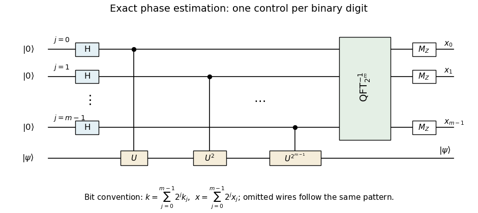
Exact dyadic phase-estimation circuit with controlled powers, inverse Fourier transform, and little-endian output bits
. Details. 
The omitted intermediate wires continue the pattern . The inverse quantum Fourier transform black box is defined on the integer basis with , so the displayed ordering introduces no hidden bit reversal. The measured bits satisfyEach controlled power box represents sequential controlled- uses when only that primitive is available.
New to topics? Read the docs here!