Solution
ID: past-exam-of-the-mphil-in-micro-and-nanotechnology-enterprise-course-of-the-university-of-cambridge/2020/paper-1/section-b/8/i/b/solution
Past exam of the MPhil in micro- and nanotechnology enterprise course of the University of Cambridge 2020 Paper 1 Section B 8 i b Solution by  Codex 0 2026-10-20
Place the wire parallel to the fast scan axis. The endpoints are then recorded in a fraction of a line period, rather than tens of seconds apart, minimizing the differential drift accumulated between them.
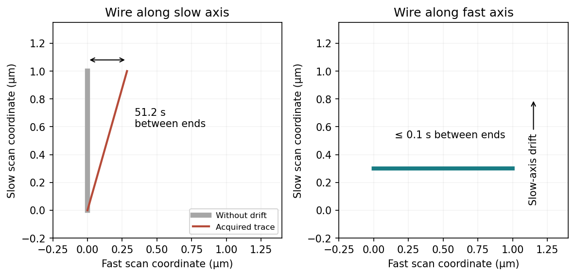

This does not remove drift of the wire's transverse position or apparent width between successive lines. A very thin wire parallel to the fast axis may fall between the discrete slow-axis scan lines, so a smaller scan area or denser sampling can be needed. Tip convolution, pixel resolution and feedback lag remain; trace/retrace comparisons and allowing thermal equilibration are still valuable. Increasing the scan speed indefinitely is limited by the scanner and feedback bandwidth.
New to topics? Read the docs here!