
A diffraction order is the integer labeling a principal constructive interference direction of a diffraction grating: adjacent elements differ in path length by wavelengths. In the normal-incidence transmission geometry described above,Positive and negative diffraction orders lie on opposite sides of the forward normal. The condition expresses the range of the sine of a real angle, so it also limits the propagating diffraction orders.
For and , . Taking the inverse sine givesThese are seven allowed propagating diffraction orders. Order would require , and would require , so neither has a propagating far-field direction. The allowed diffraction orders are equally spaced in , while their actual angles become farther apart toward grazing propagation.
Each principal peak has finite width. For the ideal uniform coherent array, the nearest zeros around order obeyThus the one-sided distance from the order direction to the first zero is . Near the first diffraction order in our example, puts the zeros at and , while puts them at and . The respective one-sided widths are and ; the full zero-to-zero widths are and . These are calculated coherent peak widths, with the slit envelope omitted, and do not describe a measured instrument response. [ref]
https://farside.ph.utexas.edu/teaching/315/Waveshtml/node93.html. Richard Fitzpatrick: Principal maxima and their neighbouring zeros, equations 10.39-10.42
.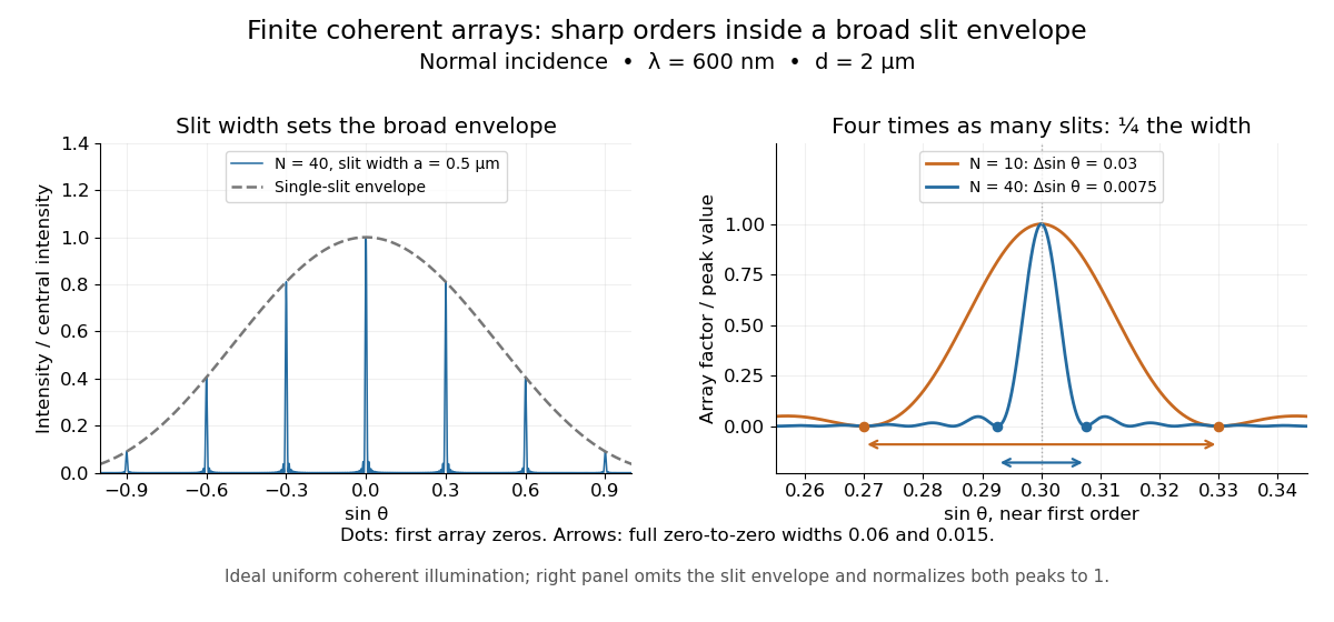

Four times as many illuminated slits therefore give a fourfold narrowing in this coordinate without moving the diffraction order. That sharper directional selection helps distinguish nearby wavelengths in a spectrograph. Actual performance also depends on illumination, optical coherence, and source width; the separate slit-limited resolving power of a grating describes the contribution of the entrance slit.
New to topics? Read the docs here!