
Incoming links: Josephson current
AC Josephson effect Updated 2025-07-16
It is called "AC effect" because when we apply a DC voltage, it produces an alternating current on the device.
By looking at the Josephson equations, we see that a positive constant, then just increases linearly without bound.
Wikipedia mentions that this frequency is , so it is very very high, so we are not able to view individual points of the sine curve separately with our instruments.
Also it is likely not going to be very useful for many practical applications in this mode.
An I-V curve can also be seen at: Figure "Electron microscope image of a Josephson junction its I-V curve".
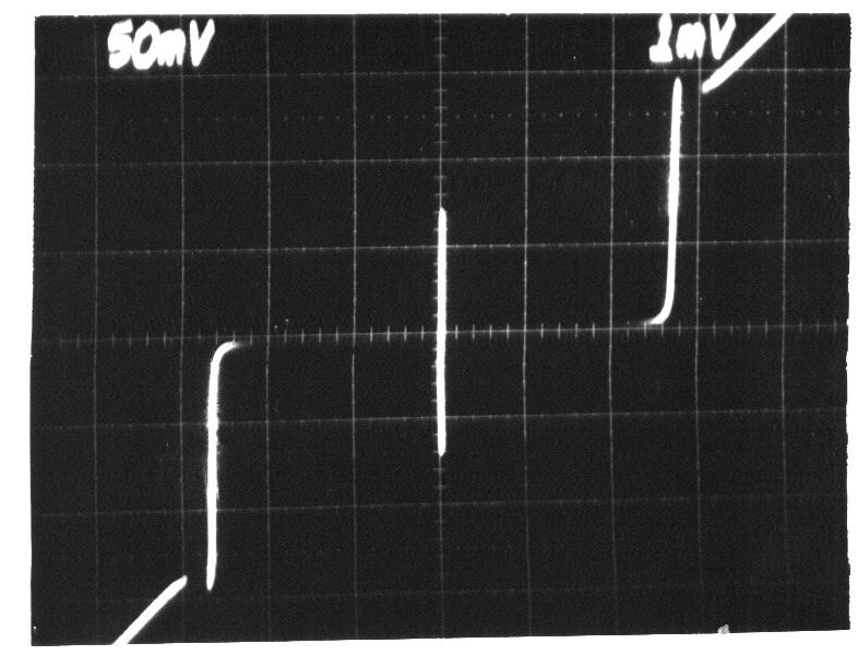
I-V curve of the AC Josephson effect
. Source. 
Voltage is horizontal, current vertical. The vertical bar in the middle is the effect of interest: the current is going up and down very quickly between , the Josephson current of the device. Because it is too quick for the oscilloscope, we just see a solid vertical bar.
Superconducting Transition of Josephson junction by Christina Wicker (2016)
Source. Amazing video that presumably shows the screen of a digital oscilloscope doing a voltage sweep as temperature is reduced and superconductivity is reached.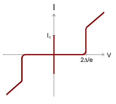
Josephson equations Updated 2025-07-16
Two equations derived from first principles by Brian Josephson that characterize the device, somewhat like an I-V curve:where:
- : Josephson current
- : the Josephson phase, a function defined by the second equation plus initial conditions
- : input voltage of the system
- : current across the junction, determined by the input voltage
Note how these equations are not a typical I-V curve, as they are not an instantaneous dependency between voltage and current: the history of the voltage matters! Or in other words, the system has an internal state, represented by the Josephson phase at a given point in time.
To understand them better, it is important to look at some important cases separately:
- AC Josephson effect: V is a fixed DC voltage