Electrical impedance is a measure of the opposition that a circuit presents to the flow of alternating current (AC) or varying direct current (DC). It encompasses not only the resistance (the opposition to direct current) but also the reactance, which accounts for the effects of capacitance and inductance in an AC circuit. ### Key Components of Impedance: 1. **Resistance (R)**: The real part of impedance, measured in ohms (Ω).
Articles by others on the same topic

Electrical impedance is the ratio of terminal electric potential difference and electric current phasors at one specified positive angular frequency . For an electrical circuit modeled as a linear time-invariant system, use the sinusoidal steady state after any decaying transient has settled. With the passive sign convention, positive electric current enters the terminal assigned positive electric potential difference. Define peak complex amplitudes byThe physical and are real; the complex numbers encode their amplitudes and wave phases. The unit of electrical impedance is the ohm, . Both phasors may instead use root mean square magnitudes, with the same ratio . A nonlinear diode can generate additional frequencies; a single then does not describe the whole response.
Write the electrical impedance in Cartesian and polar forms asHere is the resistive real part, the signed electrical reactance, and the voltage-minus-current phase difference, defined modulo a full turn. The Pythagorean theorem gives the modulus from a right triangle in the complex plane. The complex argument gives the rotation from the current phasor to the voltage phasor. Thus , while negative means electric current leads terminal electric potential difference. For , lies between and ; outside that case, use the quadrant of the complex number rather than a bare inverse tangent. The geometric magnitude and phase difference are the two pieces of the AC relation.[ref]
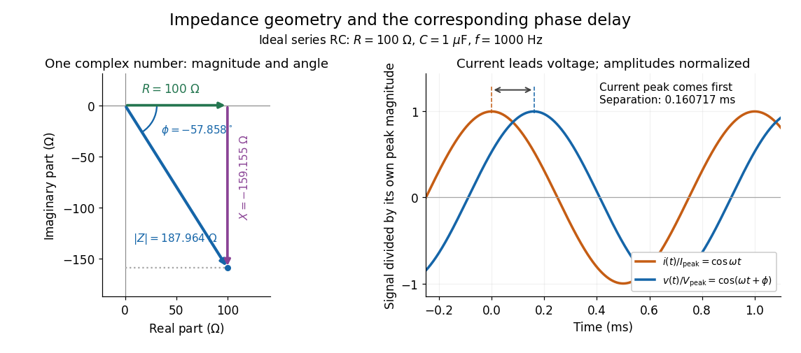
Multiplication by acts on phasors, not on instantaneous physical signals. For example, when ,The second term is in phase quadrature with electric current; it cannot be represented by pointwise multiplication when . This is the useful compression: one complex multiplication replaces separate amplitude and phase difference calculations, while the real part restores the physical signal.
An ideal resistor, inductor and capacitor have , and . Their electrical impedances add in a series RLC circuit, giving . The current amplitude is , so cancellation of the imaginary parts explains the resonant series RLC response. The component-law derivation and opposite complex exponential convention are in reactance phase convention.


Ciro Santilli distinctly remembers being taught that at basic electrical engineering school during Ciro Santilli's undergrad studies at the University of São Paulo.
It really allows you to do alternating current calculations much as you'd do DC calculations with resistors, quite poweful. It must have been all the rage in the 1950s.