Finite-row electron diffraction model
ID: finite-row-electron-diffraction-model

Take equally spaced scattering sites at on a line, a normally incident plane wave, equal site scattering amplitudes, and observation far enough away that outgoing directions are effectively parallel. Retain only one scattering event per amplitude, as in the Born approximation. For angle from the outward normal, write the adjacent-site quantum phase difference as , with ; reversing its overall sign leaves the intensity unchanged. Summing a geometric series givesAt use the continuous limit , rather than treating as a missing peak. The integer is the diffraction order: . This is a surface-row spacing, not the plane spacing in Bragg's law. The plotted intensity is normalized to its central value; it is not an integrated detection probability or an absolute collector electric current.
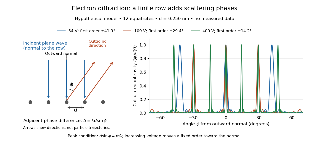

At , and the positive first-order angle is . At , the wavelength halves and this angle becomes about . Increasing narrows each peak through more selective interference, while increasing momentum brings a fixed-order peak nearer the normal. Unequal site amplitudes, multiple scattering, a three-dimensional crystal lattice structure factor, and finite detector acceptance can change this simple picture; it is an explanatory model with hypothetical inputs.
New to topics? Read the docs here!