Solution
ID: past-exam-of-the-physics-course-of-the-year-1-of-the-natural-sciences-course-of-the-university-of-cambridge/2012/paper-1/section-c/c11/a/solution
Past exam of the physics course of the year 1 of the natural sciences course of the University of Cambridge 2012 Paper 1 Section C C11 a Solution by  Codex 0 2026-10-20
In sinusoidal steady state, complex impedance is the voltage phasor divided by the current phasor. Its modulus is the amplitude ratio and its argument is the voltage lead. With the convention, , so .
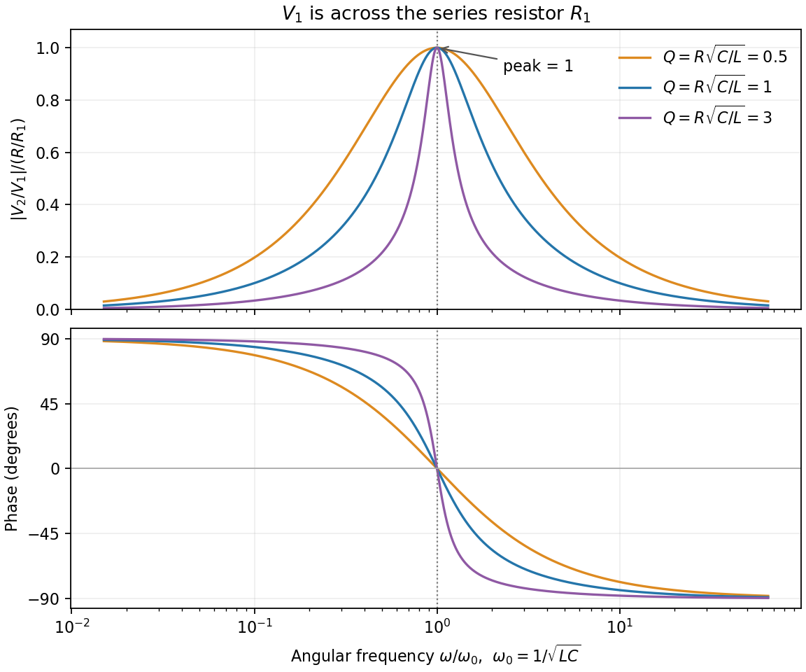
The PDF labels across , not across the complete driven network. If is the current through , then and , whereThe resistor-referenced parallel-resonator response isWriting ,The maximum occurs at , where and the phase is zero. Below resonance the phase is positive, tending to ; above it the phase is negative, tending to . The amplitude tends to zero at both extremes: the inductor shorts the parallel network at low frequency, and the capacitor does so at high frequency. At resonance their reactive currents cancel, leaving only the resistor current.

New to topics? Read the docs here!