Solution
ID: past-exam-of-the-physics-course-of-the-year-1-of-the-natural-sciences-course-of-the-university-of-cambridge/2014/paper-1/c10/solution
Past exam of the physics course of the year 1 of the natural sciences course of the University of Cambridge 2014 Paper 1 C10 Solution by  Codex 0 2026-10-20
For sinusoidal steady state with convention , complex impedance is the voltage phasor divided by the current phasor. Its modulus is the amplitude ratio and its argument is the voltage-current phase difference. Since ,The original circuit is a series RLC circuit with output across the inductor. Its transfer function isFor the original capacitance, the outputs are at and at , a ratio . The current resonance is , so the circuit favors the first transmitter.
The resistor voltage is in phase with the current; the inductor voltage leads it by and the capacitor voltage lags by . Large reactive voltages therefore nearly cancel in their phasor sum. A large inductor voltage is consistent with a small supply voltage: it is inductor voltage magnification, not power gain in a passive circuit.
Reducing the capacitance raises to , between the two transmitters. Direct evaluation gives and , respectively. Their similar detunings give approximately equal amplitudes; they are not exactly equal, partly because the numerator of also depends on frequency.
The two-tone output of a linear resonant circuit, for coherent monochromatic sources of equal input amplitude and arbitrary fixed input phases, isWith , this is approximatelyThus a rapid oscillation has a beat envelope repeating in magnitude at . The signed envelope cosine has frequency . Unequal amplitudes leave a small nonzero envelope minimum; independently drifting transmitter phases make the beating drift. No new frequency is generated by this ideal linear circuit.
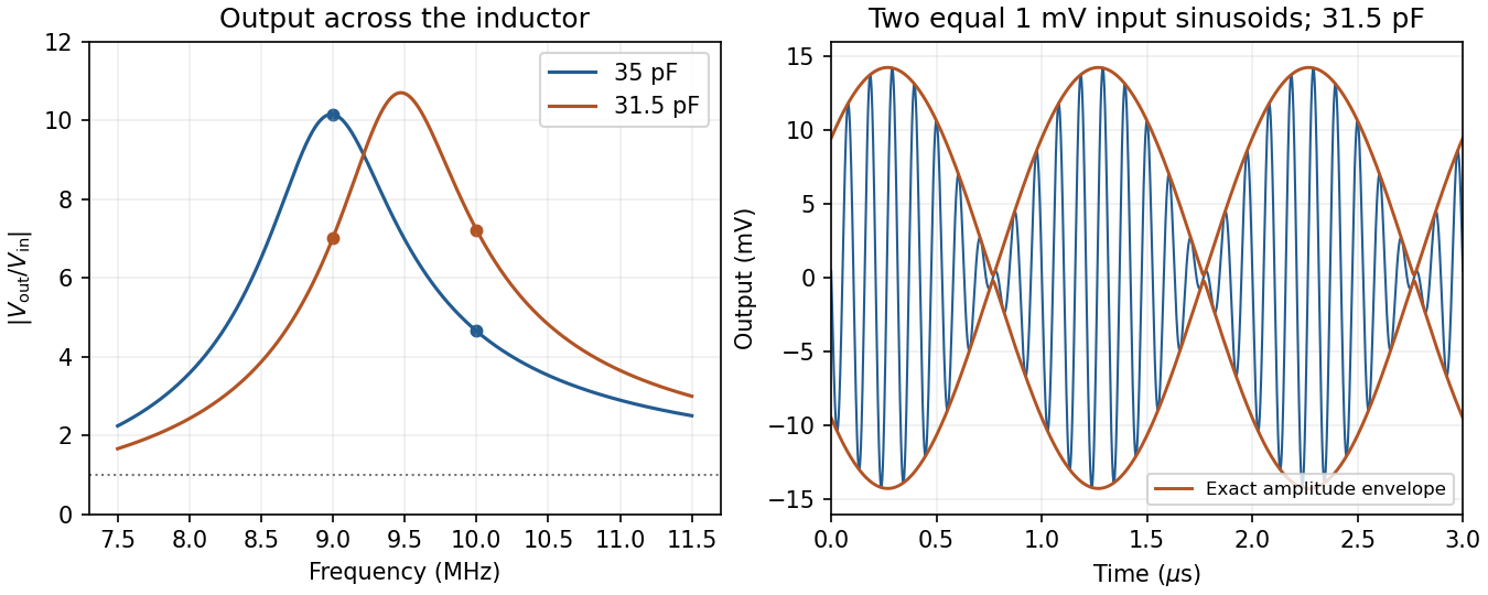
Original calculated inductor-voltage gains and illustrative two-tone output, including the circuit's frequency-dependent phase shifts
. Details. 
New to topics? Read the docs here!