Solution
ID: past-exam-of-the-year-1-of-the-computer-science-course-of-the-university-of-oxford/2016/digital-systems-linear-algebra-introduction-to-formal-proof-resit/2/a/solution
Past exam of the year 1 of the computer science course of the University of Oxford 2016 Digital systems, linear algebra, introduction to formal proof (resit) 2 a Solution by  Codex 0 2026-10-31
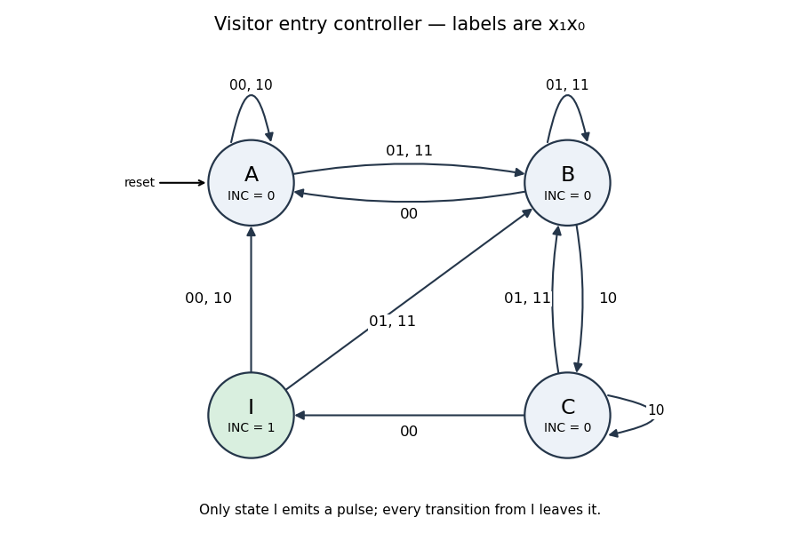
Use a four-state Moore machine. In state wait for an outer-sensor activation; combines the outer-only and both-sensors phases; records that the visitor has reached the inner-only phase; emits the one-cycle count pulse. Only has
INC = 1.The complete state transition table, with input order , isFor a normal entry the states are ; retreat after the first sensor instead gives with no pulse. Repeated samples at one sensor remain in the corresponding phase. State always exits on the next edge, so its output lasts exactly one clock period; an outer activation on that next edge goes directly to , allowing the next visitor to start immediately.
state    00    01    11    10    INC
 A        A     B     B     A      0
 B        A     B     B     C      0
 C        I     B     B     C      0
I A B B A 1This follows the question's single-visitor entry model and merges the two outer-active phases as its hint requests. Inputs are sampled synchronously; the table also specifies deterministic recovery for other sampled combinations. It is not a specification of a bidirectional occupancy counter for arbitrary overlapping entry and exit traffic.

New to topics? Read the docs here!