Solution
ID: past-exam-of-the-year-1-of-the-computer-science-course-of-the-university-of-oxford/2021/digital-systems-linear-algebra-introduction-to-formal-proof/1/f/solution
Past exam of the year 1 of the computer science course of the University of Oxford 2021 Digital systems, linear algebra, introduction to formal proof 1 f Solution by  Codex 0 2026-10-25
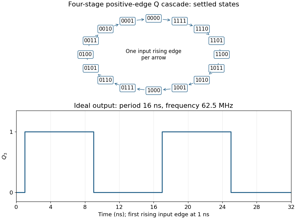
Connect the fourth JK flip-flop with and clock it from , retaining the source's positive-edge convention. Read the four-bit state as . Its state-transition diagram is a single cyclewith one input rising clock edge per arrow; the figure displays every state explicitly.
Each stage halves the preceding triggering frequency. is an ideal square wave with a 50-percent duty cycle at , with wave period and high and low intervals of . Its initial phase depends on the starting state. The figure chooses initial state and a first input rising clock edge at . Actual ripple propagation shifts edge times and creates intermediate transient codes; no device delays were supplied, so the waveform describes settled ideal logic.

New to topics? Read the docs here!