Rectangular electromagnetic waveguide
ID: rectangular-electromagnetic-waveguide

Take a straight hollow rectangular electromagnetic waveguide with vacuum interior , and axis , where . Its four walls are ideal perfect conductors. The time-dependent Maxwell equations require zero tangential electric field and zero normal oscillating magnetic field at these walls. Real metal has finite electrical conductivity, so real guides lose electromagnetic energy by Joule heating; the perfect-wall model isolates confinement and wave dispersion from that loss.
The simplest propagating transverse electric mode of a rectangular waveguide is . “Transverse electric” means , not that the magnetic field is also wholly transverse. With real peak scale , its complex amplitudes, including the common axial factor, can be writtenThe physical fields are the real parts after multiplication by . In particular, is zero at , maximal at , and independent of . At it is normal to the metal, so it need not vanish there. The electric field crosses the narrow gap, while its strength varies across the broad dimension.
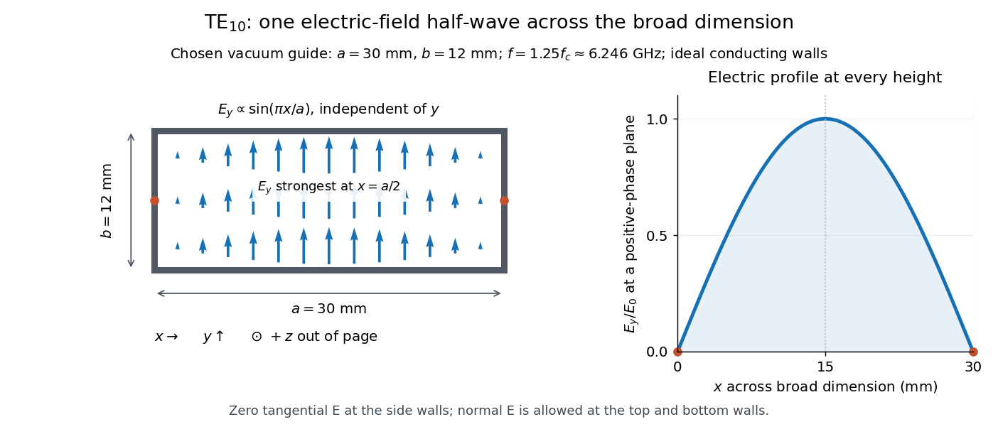
Original vacuum-filled rectangular guide: the TE10 electric-field profile across a 30 mm by 12 mm cross-section
. The arrows show the electric field at an axial plane and time where its common wave phase factor is positive; their length follows . They are field directions, not particle trajectories. The profile is uniform along and vanishes at the side walls. The guide axis points out of the cross-section. All dimensions and the operating frequency are chosen model values. Details.
For an original example choose , and , where . With , this givesHere is vacuum wavelength and is guided wavelength. The next cutoff is at ; starts at . Thus only can propagate at the chosen frequency, although a source or discontinuity can additionally excite local evanescent waves. These are calculated values, not specifications or measurements of a commercial guide.
New to topics? Read the docs here!