Barnett rotation magnetometry experiment
ID: barnett-rotation-magnetometry-experiment

The 2015 experiment used an air-driven nonmagnetic rotor containing polycrystalline gadolinium, with magnetic shielding and an external fluxgate magnetometer. Air drive reduced motor backgrounds. Measurements at 297–305 K were above the Curie temperature, at rotation frequencies up to 1.5 kHz. Reversing airflow reversed rotation and the magnetic signal; an empty capsule showed no speed-dependent signal. The readout measured stray magnetic field; geometry converted it to magnetization. Sample temperature was checked immediately after stopping. Heating and the conversion model limit inference.[ref]
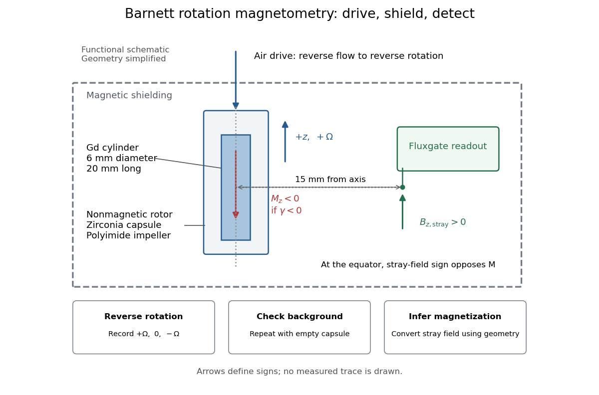

An additional analysis check follows from rotation symmetry. For signed sensor output , separateAn ideal linear Barnett effect appears in the odd component; a fixed offset appears in the even component. This is a proposed diagnostic, not a claim about the paper's processing. A background correlated with direction can also be odd: reversal alone is insufficient. Empty-rotor checks, zero-speed readings, calibration of sensor polarity, and controlled temperature changes test different errors. Equatorial stray-field sign must also be converted to magnetization sign: for an axial magnetic dipole moment, the magnetic dipole field at its equator points opposite to that magnetic moment. The apparatus diagram makes this otherwise easy-to-miss sign change visible.
New to topics? Read the docs here!