Lippmann fringe spacing
ID: lippmann-fringe-spacing

At normal incidence, let measure distance from the reflector into a uniform transparent layer with refractive index . For a monochromatic wave of vacuum wavelength , the layer wavenumber is . Represent the incident and returning electric fields by complex wave amplitudes with time factor suppressed:The time-averaged squared electric field, normalized to the incident contribution, isThis electric exposure pattern has maxima separated byThe wave phase of the reflector shifts the maxima's positions but leaves their spacing unchanged in this uniform-layer model. The electric pattern, rather than the zero net energy flux of an ideal standing wave, is the relevant exposure proxy. An imperfect mirror reduces its contrast: , where denotes this exposure proxy.
Choose and . Then the medium wavelength is and . For an ideal phase-reversing reflector, and the normalized pattern is : its first two maxima are at and . These are chosen calculations, not measured properties of a historical photographic emulsion or the optical response of Mercury.
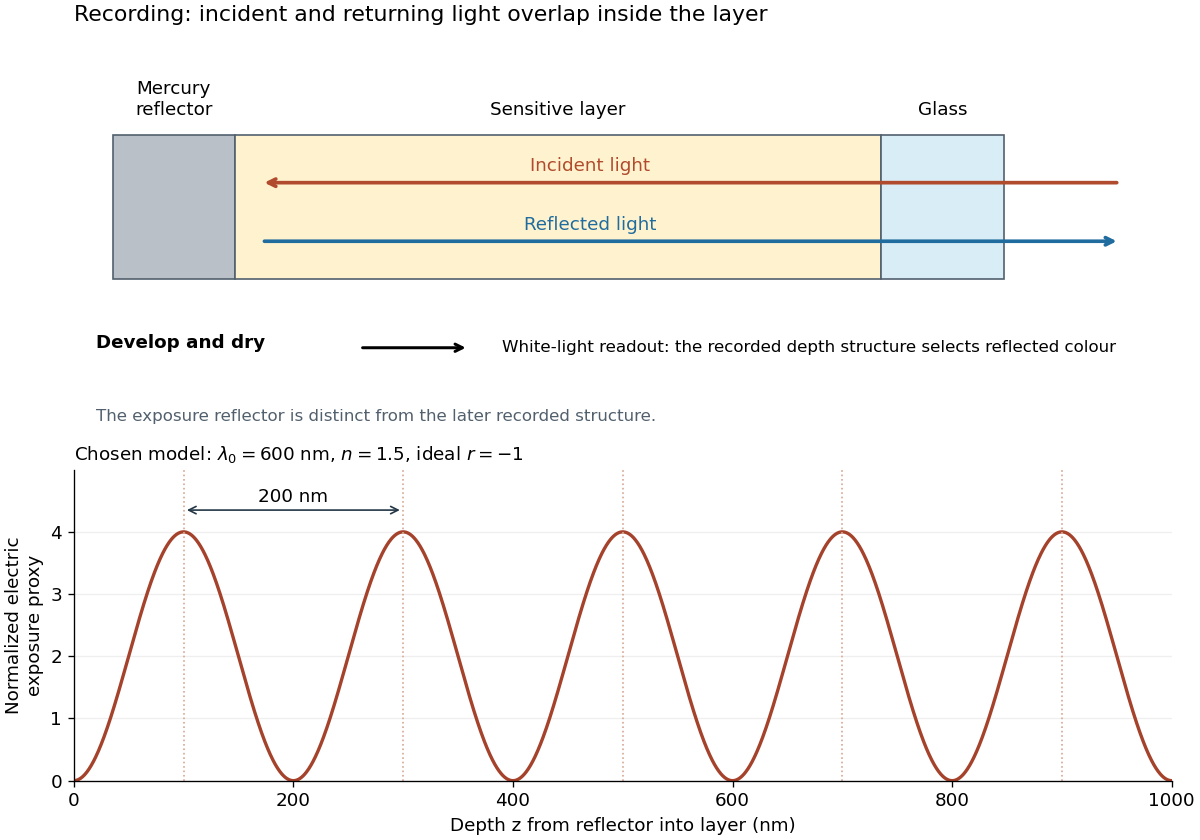

For multiple mutually incoherent wavelengths, time averaging adds exposure contributions rather than their instantaneous electric fields. In a linearized recording model,Here is incident spectral exposure density, a wavelength-dependent recording sensitivity and a model exposure response. An optical spectrum therefore writes overlapping depth oscillations, not necessarily visibly separated sheets. This is a useful connection to the Fourier transform: approximately, depth is paired with optical spatial frequency . Finite recording depth, varying sensitivity and nonlinear photographic processing prevent treating this expression as an exact inversion rule for an actual plate.
New to topics? Read the docs here!