Thomson electron transmission diffraction experiment
ID: thomson-electron-transmission-diffraction-experiment

Alongside the 1927 Davisson–Germer experiment, George Paget Thomson developed an independent transmission test. Alexander Reid first used celluloid; Thomson used thin metal films. A narrow Electron beam crossed a film about thick, reaching a photographic plate perpendicular to the beam. Rings appeared. Accelerating voltages of – set the de Broglie wavelengths; metal structures known from X-ray diffraction allowed quantitative comparison. A downstream magnetic field deflected ring-forming Electrons like those passing through holes, identifying the carriers as Electrons rather than X-rays. Celluloid's uncertain structure limited its quantitative interpretation.[ref]
The Davisson–Germer experiment uses crystal reflection and angular electric current scans; this transmission camera records a spatial pattern behind the specimen. Both probe interference in electron diffraction, with different specimen preparations and readouts. A developed photographic plate records accumulated detections, not a direct image of the wavefunction.
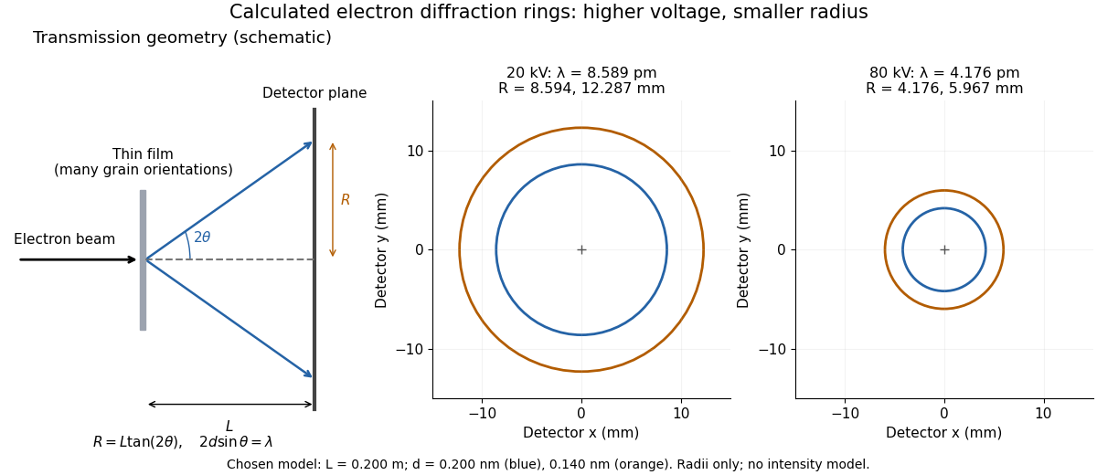
Why rings? In an ideal film containing many small crystals with uniformly distributed orientations, a family of lattice planes with spacing can satisfy Bragg's law at every azimuth about the incident beam. First-order elastic scattering then forms a cone of opening half-angle , where . A flat detector a distance downstream cuts this cone in a circle:The last expression requires small scattering angles. It explains a useful control: hold the specimen and camera distance fixed, increase accelerating voltage, and the ring radii should shrink with the electron accelerating-voltage wavelength. It predicts positions, not intensities: preferred crystal orientations, film thickness and repeated quantum scattering can alter a real pattern.
For a chosen example, take and . The exact relativistic electron accelerating-voltage wavelength gives at and at . The corresponding exact ring radii are and . These are calculated examples with chosen spacings and camera distance, not Thomson's measurements. The higher voltage lies outside the range quoted from his lecture, deliberately illustrating a prediction rather than reconstructing his data.

New to topics? Read the docs here!