A logic hazard is a transient output error caused by unequal propagation delays along paths in a Boolean circuit. A static hazard temporarily changes an output that should remain constant; a dynamic hazard introduces extra transitions when the output should change once. A steady-state truth table records final values and therefore does not describe these timing effects.
For example, implement with AND gates, an OR gate and a NOT gate. With , changing should leave . But if the first product falls before the second rises, both OR inputs can momentarily be zero. Adding the redundant term gives : it does not change the Boolean function, by the consensus theorem, and remains one throughout that single-input transition. This argument assumes the other inputs remain fixed and the circuit begins settled. Simultaneous input changes and more general implementations require their own timing analysis.
A logic hazard in which an output intended to remain one briefly falls to zero. In a sum of products, cover every adjacent pair of one-cells in a Karnaugh map with a common product implicant. That term omits the changing input and remains one throughout the transition, holding the OR output high regardless of the other path delays. This argument assumes one input changes at a time and the circuit starts settled.
For a concrete circuit, let , , , and . Give every gate, including each inverter, propagation delay 10 ns. Starting from , lower at time zero. Signal falls at 10 ns, while rises only at 20 ns. Their gap passes through the two OR gates, making fall during 30–40 ns even though its steady-state value remains one.
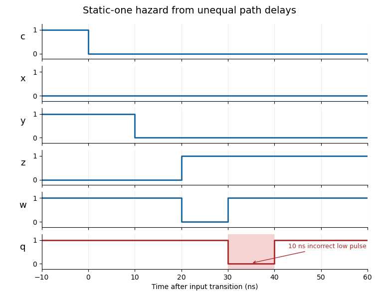
A static-one logic hazard from unequal inversion and product paths
. Details. 
Adding the two consensus theorem products and preserves the Boolean function and holds the output high across every potentially hazardous single-input transition. The resulting five-term expression factors as . When a change of could leave the output steadily one, and keep the second product steadily one. In the zero-to-zero case with changing , and keep both output products zero. Changes of use only one polarity each and therefore have no opposite-polarity race. This factored implementation uses three OR gates, two AND gates and two NOT gates, with a 40 ns maximum input-to-output path at the stated delays.
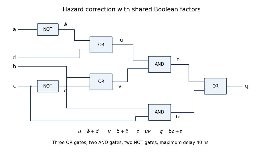
A shared-factor implementation of the consensus theorem correction
. Details. 
Articles by others on the same topic
There are currently no matching articles.