A Boolean circuit whose current output depends only on its current input, with no stored state or feedback dependency. Its delay is bounded by the longest input-to-output path of logic gates. This differs from a synchronous sequential circuit, whose output can depend on state stored at earlier clock edges.
A combinational logic circuit mapping a binary input code to selected output lines. In a one-of- register-address decoder, line is asserted exactly when the address equals , optionally combined with an enable. This selects which processor register may capture a common write-data word.
A logic hazard is a transient output error caused by unequal propagation delays along paths in a Boolean circuit. A static hazard temporarily changes an output that should remain constant; a dynamic hazard introduces extra transitions when the output should change once. A steady-state truth table records final values and therefore does not describe these timing effects.
For example, implement with AND gates, an OR gate and a NOT gate. With , changing should leave . But if the first product falls before the second rises, both OR inputs can momentarily be zero. Adding the redundant term gives : it does not change the Boolean function, by the consensus theorem, and remains one throughout that single-input transition. This argument assumes the other inputs remain fixed and the circuit begins settled. Simultaneous input changes and more general implementations require their own timing analysis.
A logic hazard in which an output intended to remain one briefly falls to zero. In a sum of products, cover every adjacent pair of one-cells in a Karnaugh map with a common product implicant. That term omits the changing input and remains one throughout the transition, holding the OR output high regardless of the other path delays. This argument assumes one input changes at a time and the circuit starts settled.
For a concrete circuit, let , , , and . Give every gate, including each inverter, propagation delay 10 ns. Starting from , lower at time zero. Signal falls at 10 ns, while rises only at 20 ns. Their gap passes through the two OR gates, making fall during 30–40 ns even though its steady-state value remains one.
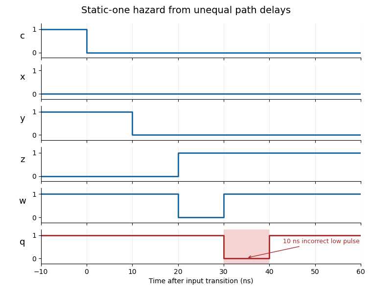
A static-one logic hazard from unequal inversion and product paths
. Details. Adding the two consensus theorem products and preserves the Boolean function and holds the output high across every potentially hazardous single-input transition. The resulting five-term expression factors as . When a change of could leave the output steadily one, and keep the second product steadily one. In the zero-to-zero case with changing , and keep both output products zero. Changes of use only one polarity each and therefore have no opposite-polarity race. This factored implementation uses three OR gates, two AND gates and two NOT gates, with a 40 ns maximum input-to-output path at the stated delays.
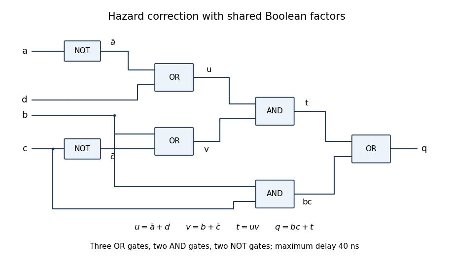
A shared-factor implementation of the consensus theorem correction
. Details. The elapsed time between a change at a logic gate's input and the corresponding settled change at its output, under specified loading and transition conditions. Dependent gate delays add along a path. The combinational critical path gives the longest such input-to-output path; reconvergent paths of unequal delay can produce a logic hazard even when the final Boolean function value does not change.
The combinational critical path is a longest propagation-delay path through a combinational logic circuit. Register-to-register clock timing also includes launch delay, setup time and clock uncertainty. Putting two functional units in series adds their dependent delays; operating them in parallel instead contributes the slower branch plus any subsequent selection delay.
A barrel shifter moves a machine word by a variable number of bit positions through a bounded-depth combinational logic circuit. For a -bit machine word, cascade banks of multiplexers selecting optional shifts of . The binary shift-amount bits select the stages; the chosen distances add. Logical shifts fill vacated positions with zero, whereas bit rotations reconnect the discarded positions. A 32-bit logical barrel shifter can use five banks of 32 two-input multiplexers.
The number of zero bits before the first one, reading a fixed-width binary representation from its most significant bit. The all-zero -bit input has count . Thus , and ; the width is part of the definition.
For leading-zero count, inspect a word's bytes from most significant to least significant. Every zero byte contributes eight; the first nonzero byte contributes its table value in the title. If all bytes are zero, a word of width contributes . Defining the zero table entry explicitly makes the all-zero argument a regular case rather than an out-of-range logarithm.
For a block of bits, encode its count leading zeros result as a zero flag followed by low count bits . An all-zero block has ; otherwise . Two half-block encoders supply flags and low counts . Combine them using , , and for . A one-bit leaf has and no low count bits. Checking whether the upper half is nonzero, only the lower half is nonzero, or both halves are zero proves the formula.
All count bits are selected in parallel, so for circuit depth. The circuit size satisfies ; summing the work over levels gives . Sharing the all-zero flags avoids a serial adder along the critical path.
A Boolean circuit computing the sum of binary representations, possibly including input and output carry bits. Its delay depends on how carries are propagated; specifying an adder does not by itself imply constant circuit depth as the input width grows.
A combinational logic circuit adding two input bits to a sum bit and carry bit . An exclusive or gate and an AND gate implement it. The identity follows by checking the four input pairs. A half adder has no input carry, so adding three equally weighted bits needs a different circuit or multiple stages.
A selector that routes one of several inputs to its output according to control bits. The displayed two-input version selects when and when . A word selector applies the same control bit to parallel one-bit multiplexers; its circuit size grows with the word width while its added circuit depth remains constant.
A combinational logic device comparing two fixed-width binary representations. For unsigned inputs , a two-output encoding is exactly when and exactly when . Equality gives ; is unreachable. A one-bit implementation is , .
A digital comparator processes one pair of bits per clock cycle, storing a comparison result in a finite-state machine. For least-significant-first unsigned input, a new unequal pair overrides the stored result, while equal bits preserve it: the newest unequal pair has the greatest place value seen so far.
To combine more and less significant digital comparators, compute and use the displayed formulas. Unequal upper blocks decide the order, because their difference outweighs every possible lower-block difference; equal upper blocks delegate the decision to the lower block. This is an associative operation on the three comparison outcomes. A balanced binary tree of these combinations has circuit size and circuit depth for -bit inputs.
Articles by others on the same topic



Combinational logic refers to a type of digital logic circuit whose output is a pure function of the present state of its inputs. In other words, the output at any given time depends only on the combination of inputs at that same time, without any memory of past inputs. This is in contrast to sequential logic, where the output depends on both the current inputs and the state of the system (which may be influenced by past inputs).