Place the two slits at transverse coordinates and . Let the source point have coordinate and the observation point coordinate , both measured in the same transverse direction. The total lower-slit path minus upper-slit path isThe last line uses the paraxial approximation at both source and screen. The source assumptions give ; the screen expression also assumes . Reversing the source-coordinate orientation would change the sign of , without changing the uniform-source result.
At the slits, the differential path delay from a source element is . Across the full filament its range is . Keeping all these phases nearly equal therefore requiresThis is a sufficient near-unit-spatial coherence condition, rather than a necessary condition for any observable interference. That distinction follows quantitatively below.
Different small elements of a thermal filament are mutually incoherent, so their wave intensities add. The two paths from one element are coherent. If that element supplies the same intensity through each slit, the superposition principle giveswhereIntegrating intensities over the incoherent source givesAdding complex amplitudes across different source elements instead would incorrectly assume mutual optical coherence of the entire filament.
The printed is a signed local modulation, not the usual fringe visibility. From the maximum and minimum of this scanned fringe pattern, the interferometric visibility isIt is independent of the screen's fringe phase and is nonnegative. For a concrete distinction, take and : the printed is zero at that observation point, while the pattern has contrast . The same example has , which is not much smaller than , yet substantial interference survives. When the signed coherence factor is negative, bright and dark fringe positions interchange; the contrast remains its absolute value. This is the distinction between signed coherence and fringe visibility.
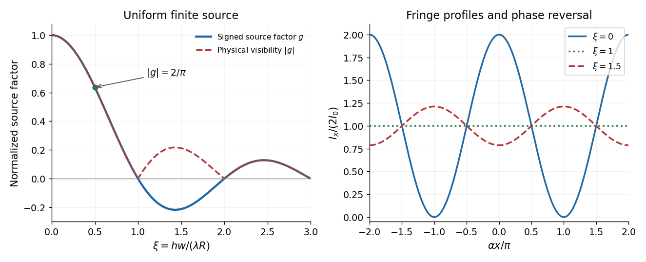
Finite source width changes fringe contrast and can reverse fringe phase
. Original uniform-filament calculation. The signed source factor and its absolute value differ; the latter is the standard interferometric visibility. The fringe traces illustrate high contrast, vanishing contrast, and phase reversal. Details.
Articles by others on the same topic
There are currently no matching articles.