In a contractible region, the Maxwell equations and the Poincaré lemma imply the existence of a magnetic vector potential such that . Faraday's law of induction then givesThe expression in parentheses is a gradient there, so a scalar electric potential can be chosen withThese statements are local, or global when the domain has the required topology and the electromagnetic fields are regular. A nonzero flux through a topologically nontrivial closed surface can obstruct a single globally defined vector potential, even though local expressions remain valid. The electric potential and magnetic vector potential are not unique: and leave both electromagnetic fields unchanged.
For the Lorenz gauge condition , Gauss's law becomesThe Ampere-Maxwell law givesCancel the two gradient terms using the Lorenz gauge condition. HenceBoth potential equations have the same d'Alembert operator, with their respective charge density and current density sources. In a source-free region these are homogeneous wave equations with propagation speed .
Let be the mean path length in the core. Neglect leakage and fringing across the narrow air gap, and assume a cross-section small compared with . Continuity of normal magnetic flux density then gives the same tangential magnetic field magnitude in the core and gap. Ampère's circuital law for the magnetic field strength isFor a linear core, and , givingHere follows the winding's right-hand rule. The gap has much larger than the core when , although is approximately continuous. Equivalently, the core and gap magnetic reluctances add in series.
On a magnetic hysteresis loop, remanence is the nonzero remaining at after magnetizing the sample. The normal magnetic coercivity is the magnitude of reverse at which on that branch. The intrinsic magnetic coercivity instead refers to zero magnetization; these two conventions should not be confused. A comparison of coercive with remanent requires a unit conversion or a specified constitutive scale, because their SI units differ. A soft ferromagnet is understood here to have a narrow loop and small coercive field.
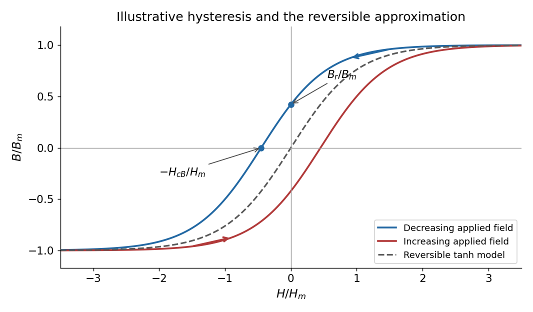
Magnetic hysteresis and the reversible tanh approximation
. Original illustrative magnetic hysteresis loop with the remanent magnetic field and normal coercive magnetic field strength marked. The dashed single-valued curve is the reversible approximation used in the calculation, rather than a hysteresis branch. Details.
Use the stated single-valued constitutive equation for the calculation. Inverting it gives , soSince , the small-signal response of a gapped magnetic core isThe small-field core magnetic permeability is . Strictly, is a reversible approximation: at it has , so it cannot itself model nonzero remanence. The displayed loop and this constitutive approximation serve different purposes. Keeping a genuinely remanent branch would generally add a history-dependent offset; it would not imply through the origin.
Take as the centre-to-centre separation and . Use the ideal lossless two-conductor transmission line model, with nonmagnetic surroundings and negligible internal-wire inductance. Opposite line charges and approximate the cylindrical conductors when . Integrating their electric fields, or adding their logarithmic electric potentials, gives the potential differenceThis is the two-wire capacitance at large separation. For opposite electric currents and , the magnetic fields between the wires add. The linked magnetic flux per unit length is approximatelyThus the external inductance of a thin two-wire line is . The lossless telegrapher's equations give a forward wave with , so its characteristic impedance isThe product also gives the propagation speed , an independent consistency check. The exact ideal external-field geometry replaces by . If the wire separation were specified between surfaces, its centre separation would be , with the same leading large-separation result. Finite electrical conductivity and internal-wire magnetic energy require a more detailed line model.
Snell's law is , with both angles measured from the interface normal vector. Let be the meridional ray's angle to the optical axis inside the core and let be the incident medium's refractive index. At the entrance face,At the cylindrical wall the angle of incidence is . For , the critical angle for total internal reflection satisfies . At the limiting accepted ray,Consequently the optical fiber acceptance angle obeysThe requested expression follows for incidence from air, , provided the right-hand side is at most one. Strict total internal reflection occurs inside this limiting cone. The derivation uses the standard meridional ray model; skew launches need additional geometry.
If , every forward entrance angle allowed by this ideal model meets the side-wall condition, and the limiting half-angle is , rather than an undefined inverse sine. For example, , , gives . Thus the unsaturated printed formula is not valid for every possible pair of refractive indices.
Use the thin lens sign convention in which a real object on the incident side has positive object distance, a real image on the outgoing side has positive image distance, and a converging lens has positive focal length. The first image distance isFor the image distance for two separated thin lenses, the second lens has object distance , which can be negative when its intermediate object is virtual. Applying the thin lens equation again givesThe image is beyond the second lens when ; denotes a virtual image on its incident side. A vanishing denominator with nonzero numerator denotes an image at infinity. The rational expression also supplies appropriate limits when the first image is at infinity; for example, gives for finite nonzero focal lengths.
As , the effective focal length is andFor a real incident object, , and positive , the real-image condition is exactly , yielding the requested inequality. This includes two converging lenses. The positivity assumption matters: with and , one has and , but is virtual. If , the touching pair has zero net optical power and produces no real image of this real object in the ideal thin lens model.
Put the plate behind the slit at transverse coordinate , and let positive screen coordinate point toward that slit. The extra optical path length isIn the paraxial approximation, the covered path minus the uncovered path has total optical path difference . Its zero determines the shifted central interference fringe:toward the slit covered by the plate. Moving toward that slit shortens its geometric path and compensates the extra delay in the plate.
More generally, the phase difference is , so every interference fringe translates by the same in this approximation. The spacing is unchanged, and the shift corresponds to fringe periods. For an ideal uniform transparent plate that changes only the wave phase, the envelope and interferometric visibility are unchanged. Reflection losses or unequal transmission through a real plate could additionally reduce the interferometric visibility; those are separate amplitude effects. No numerical wavelength is needed for the physical displacement of the zero-order fringe.
Write and for homogeneous scalar material constants, and use . Taking the curl of Faraday's law of induction and substituting the Ampere-Maxwell law givesThe vector calculus identity for a double curl therefore yieldsThe second term represents electric current response, rather than displacement current. A dispersive is used in the frequency domain; its general time-domain counterpart is a temporal response convolution.
For the convention , the plane wave equation isDecompose the electric field into components parallel and perpendicular to . With , the longitudinal eigenvalue is and each transverse eigenvalue is ; thus the determinant is . For a transverse electromagnetic wave, andwhen and the background . A real dissipative electrical conductivity generally makes complex, with the decaying branch chosen for a passive medium.
For a cold, collisionless, unmagnetized plasma, treat ions as stationary and write for the magnitude of the elementary charge. The electron equation of motion is , soThis reactive response includes no collision-induced Joule heating. Substitution into the transverse dispersion relation givesThe quantity is the electron plasma frequency. The refractive index is real above this cutoff; below it, the wave is evanescent. The electron response is represented here by , so it must not also be counted a second time in the background permittivity.
For a nonzero longitudinal component, taking the dot product of the matrix equation with instead gives . The same cold plasma response makes , henceAt nonzero , the remaining equation forces to be parallel to , and Faraday's law of induction gives . These are electrostatic Langmuir waves, with no dependence of angular frequency in the zero-temperature model. Equilibrium neutrality does not forbid their perturbed charge density; Gauss's law requires such a density when .
Let be the uniform charge density and take . Rigid rotation produces current density . The magnetic dipole moment isSpherical symmetry gives , while . ThereforeIt is parallel to the angular velocity for positive and antiparallel for negative . The fully signed magnitude statement is ; the printed magnitude assumes positive and positive angular speed.
Axisymmetry permits a purely azimuthal magnetic vector potential, , with . For the source's associated Legendre function convention, , since its definition omits the Condon–Shortley phase. The given differential operator reduces toInside the sphere, . Since the radial operator maps to , the particular coefficient is . Regularity at the origin and decay at infinity giveThere is no surface sheet electric current, so both normal and tangential magnetic field components are continuous at . Usingthis is equivalent to continuity of and . The two equations give and . ThusIn the homogeneous expansion, , in their respective interior and exterior regions; all higher angular orders vanish. Indeed, matching the regular and decaying terms with zero source at forces both coefficients to zero. The outside magnetic field is exactly the magnetic dipole field of , not merely its leading far-field approximation. For a positive moment along , , which is the printed cross-product magnitude expression.
For the flux coupling of a rotating charged sphere to a circular loop, take a loop of radius in the equatorial plane and use Stokes theorem on the regular full vector potential, evaluated around the rim. Its linked magnetic flux isWith , the mutual inductance defined using this effective electric current isIntegrating an ideal magnetic dipole field through the entire disk would incorrectly use its singular expression inside the actual sphere; the rim calculation avoids that error.
For the prescribed time dependence, the quasistatic Faraday's law of induction result and the purely resistive loop approximation givePositive loop electric current is defined to produce a positive magnetic dipole moment, so the minus sign is Lenz's law. This assumes negligible retardation and , where is the loop's self-inductance. If that is not negligible, the governing equation is instead ; alone is insufficient for the exact dynamic response.
Let be the single-mirror power reflectivity and the propagation angle inside the gas. Define as the vacuum wavelength. Successive transmitted complex amplitudes differ by a round-trip factor , where, for real dielectric reflection coefficients whose product has positive sign,The cosine arises by comparing successive emerging rays on the same outgoing wavefront; it is not the literal zigzag distance . Equivalently, the round-trip phase is . If the source's is the angle in external air, Snell's law gives andIf denotes the internal angle, simply set .
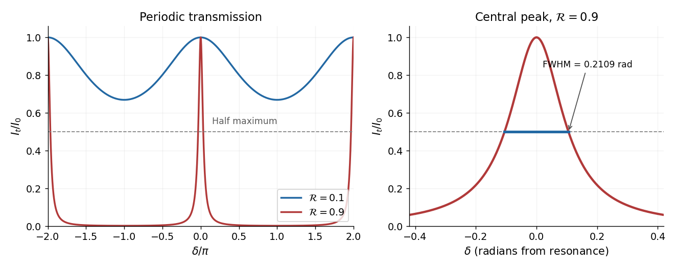
For identical lossless mirrors, their power transmission is . In an energy-normalized amplitude convention this is ; more general interface amplitudes require the corresponding wave impedance factors. The geometric series of transmitted amplitudes givesHenceThis is Fabry–Pérot transmission from multiple reflections.[ref]
Fabry-Perot Interferometer, University of Washington Physics 331. Theory equations (1)–(2), including the coefficient of finesse
At normal incidence, for nondispersive and zero net reflection phase modulo , the resonance condition is . The resonance frequencies and free spectral range areFor finite the resonances have finite width, and transmission away from them is nonzero. Thus “only discrete frequencies” is an ideal high-reflectivity description of the selected resonances, not an exact statement about the support of the transmitted spectrum. For example, at still gives .
At half the unit peak, . Measuring the phase displacement from a resonance yieldsThe last expression is the high-reflectivity approximation, with finesse . At , the full phase width is about radians and . At , the minimum transmission is , so the trace never reaches half the peak and this full width at half maximum is not defined. The exact half-maximum condition requires .

For the absorbing Fabry–Pérot mirror phase and transmission, write and let be the power transmission of one mirror. Optical absorption makes . The transmitted intensity becomesHere the phase formula is at normal incidence. The peak is reduced below unity, while a change in changes the width. The complex reflection phase also moves the resonances: if is approximately constant,If either or depends on frequency, this is an implicit condition and the free spectral range need not be constant. No numerical shift is determined without the mirrors' optical response.
Place the two slits at transverse coordinates and . Let the source point have coordinate and the observation point coordinate , both measured in the same transverse direction. The total lower-slit path minus upper-slit path isThe last line uses the paraxial approximation at both source and screen. The source assumptions give ; the screen expression also assumes . Reversing the source-coordinate orientation would change the sign of , without changing the uniform-source result.
At the slits, the differential path delay from a source element is . Across the full filament its range is . Keeping all these phases nearly equal therefore requiresThis is a sufficient near-unit-spatial coherence condition, rather than a necessary condition for any observable interference. That distinction follows quantitatively below.
Different small elements of a thermal filament are mutually incoherent, so their wave intensities add. The two paths from one element are coherent. If that element supplies the same intensity through each slit, the superposition principle giveswhereIntegrating intensities over the incoherent source givesAdding complex amplitudes across different source elements instead would incorrectly assume mutual optical coherence of the entire filament.
The printed is a signed local modulation, not the usual fringe visibility. From the maximum and minimum of this scanned fringe pattern, the interferometric visibility isIt is independent of the screen's fringe phase and is nonnegative. For a concrete distinction, take and : the printed is zero at that observation point, while the pattern has contrast . The same example has , which is not much smaller than , yet substantial interference survives. When the signed coherence factor is negative, bright and dark fringe positions interchange; the contrast remains its absolute value. This is the distinction between signed coherence and fringe visibility.
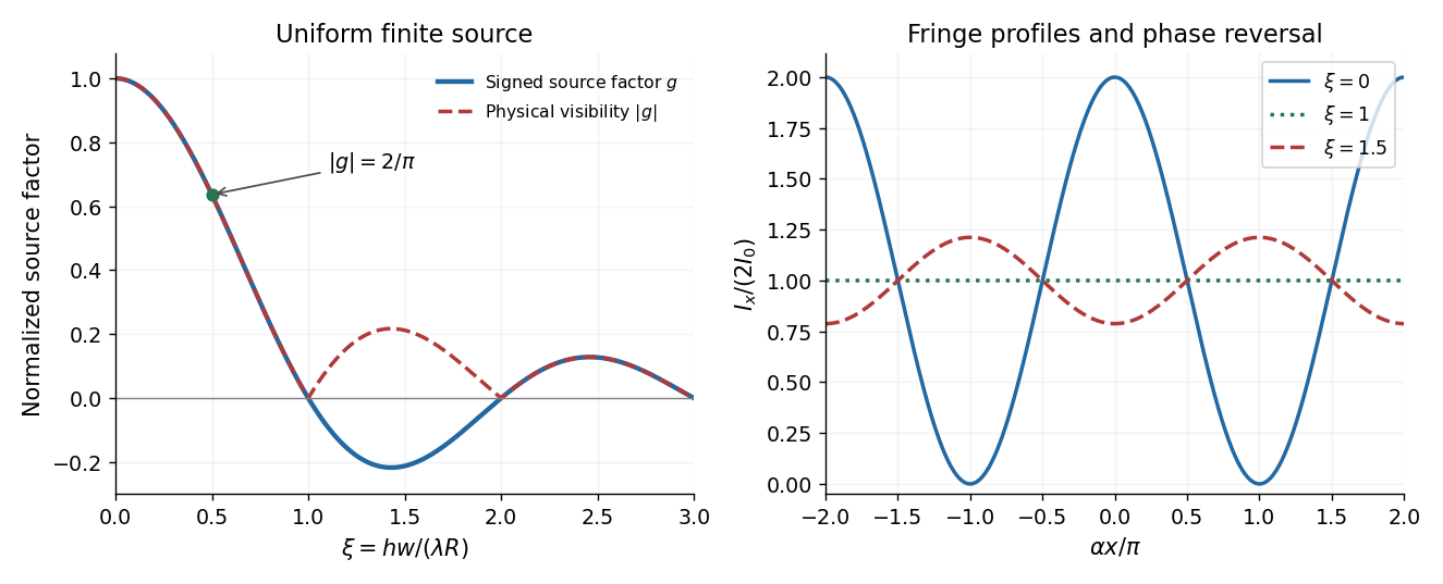
Finite source width changes fringe contrast and can reverse fringe phase
. Original uniform-filament calculation. The signed source factor and its absolute value differ; the latter is the standard interferometric visibility. The fringe traces illustrate high contrast, vanishing contrast, and phase reversal. Details.
Articles by others on the same topic
There are currently no matching articles.