Features only a few tens of nanometres wide lie below the ordinary visible-light diffraction limit, approximately . The microscope cannot resolve individual rods, and unpolarized illumination does not directly reveal the orientation-dependent optical response. Scanning electron microscopy and atomic force microscopy can resolve the surface pattern. Transmission electron microscopy is another possible choice if a suitably thin specimen can be prepared.
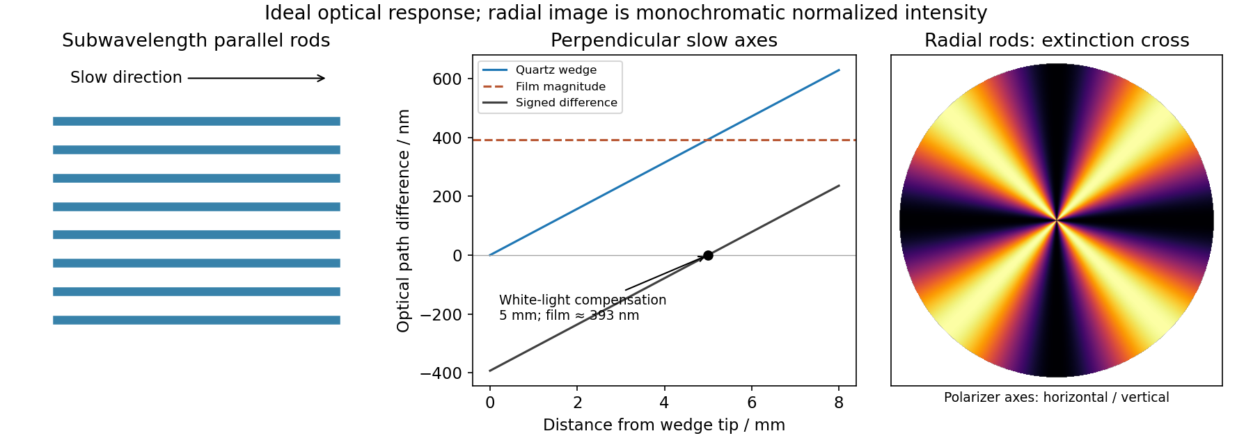
An optically isotropic film changes the phase of both transverse polarization components equally, so crossed polarizers still extinguish the transmitted light. The etched rod-and-gap composite has form birefringence: its effective permittivity depends on the direction of the electric field, even when the constituent material is intrinsically isotropic. In a simple subwavelength lamellar model,The precise effective-medium formula changes with rod geometry, but the anisotropy remains. Resolving incident light along the two principal directions produces a phase retardation. An ideal lossless specimen between crossed polarizers transmitswhere is the intensity after the first polarizer. Extinction occurs when a principal direction follows either polarizer; transmission is strongest near .
At distance from its tip, the wedge thickness is . Its optical path difference is thereforeThe perpendicular slow directions make the two retardances subtract. A white-light black compensation fringe is the zero-order cancellation, so the film retardance has magnitude approximately , with its slow direction along the rods. This interpretation assumes the observed fringe is the white-light compensation fringe; a single monochromatic dark fringe alone would have an integer-order ambiguity. Without the wedge, the wavelength dependence of selectively transmits visible wavelengths and gives the film its interference colour.
The local slow direction follows the radial rods. Between crossed polarizers, the angular factor is , so radial directions parallel to either polarizer are dark. The pattern is a Maltese cross in polarized-light microscopy, with four bright sectors separated by dark arms parallel to the polarizer directions. Its colours depend on the local optical path difference; tapering rods or changing fill fraction can make this vary with radius. The cross belongs to the local radial-axis pattern and does not imply a conoscopic interference figure.

Articles by others on the same topic
There are currently no matching articles.