Permittivity describes how an electric field and a material's electric polarization combine into the electric displacement field. In a static, local response with linearity and isotropy, and no electric polarization at zero electric field, the constitutive equation isHere is vacuum permittivity, while is the relative permittivity, a dimensionless quantity. The SI unit of permittivity is farad per metre, : multiplying it by an electric field in gives an electric displacement field in . A larger positive permittivity lets the same parallel-plate capacitor hold more plate electric charge at the same electric potential difference.
The material contribution is electric polarization , the electric dipole moment per unit volume. The electric displacement field and electric susceptibility satisfySubstitution gives the first constitutive equation. The electric field here is the averaged, total field inside the material, not just the field of the external plate electric charges. The continuum approximation averages over many chemical atoms or molecules; locality means that the electric polarization at a position depends on the electric field there. Static equilibrium, fixed material conditions and sufficiently small electric fields are needed for this scalar proportionality. [ref].
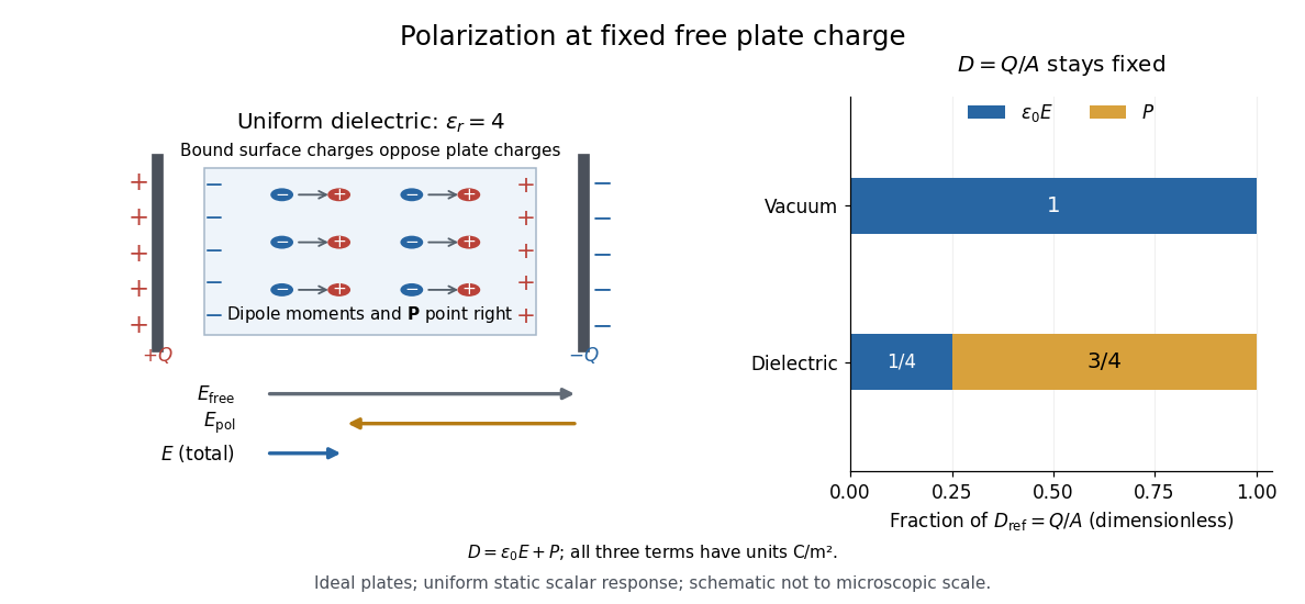
For an ideal parallel-plate capacitor completely filled by a uniform dielectric, hold the free plate electric charge magnitude fixed and neglect the fringing field of a capacitor. Writing for the plate area, Gauss's law gives . ThusThe electric dipoles point along the electric field. Their surface electric charges, described by polarization density, oppose the field from the free plate electric charges. For a hypothetical dielectric with , the internal electric field is one quarter of its vacuum value, while . At fixed electric potential difference instead, the internal electric field stays approximately and the plate electric charge grows fourfold. These are different experimental constraints. [ref]
https://www.feynmanlectures.caltech.edu/II_10.html#Ch10-S3. Feynman, Leighton and Sands, II.10–3, equations (10.5)–(10.11): polarization surface charge, field reduction and capacitance
.
Permittivity is a useful material summary, not a universal constant of the material under every condition. Temperature, frequency and electric field strength can change the response. In a linear anisotropic dielectric, permittivity is a tensor, , so the electric displacement field need not be parallel to the electric field. At nonzero frequency, delayed electric polarization requires complex permittivity and may produce dielectric loss. [ref].
The permittivity tensor is the linear material-response matrix relating electric displacement field to electric field at a specified frequency. An isotropic local medium has . A magnetically biased transparent medium can have an imaginary antisymmetric transverse contribution; its eigenmodes can have opposite circular polarizations and different refractive indices.
A dielectric is a material in which an electric field produces electric polarization while transport of electric charge is sufficiently small for the intended use. An insulating solid in a capacitor is an example; real dielectrics can still have dielectric loss and nonzero electrical conductivity.
The important distinction is between rearranging bound electric charge and transporting mobile charge carriers through the specimen. Bound electric charges can move a little within a chemical atom or molecule, or an existing electric dipole can turn. Their averaged electric dipole moments produce electric polarization even if there is negligible steady electric current between the electrodes. A changing electric polarization does give a bound current; the absence of steady conduction does not mean that the material is electrically unresponsive.[ref]
For uniform electric polarization in a rectangular slab, polarization density gives zero bound volume charge density in the interior and opposite bound surface charge densities on the left and right faces. The electric charge has been redistributed, not created. More generally, the divergence theorem makes the cancellation explicit:Here is the outward normal vector on the material boundary. This accounts for both bound volume charge density and bound surface charge density; omitting either can falsely suggest that an initially neutral dielectric acquired net electric charge.
An electrical insulator between capacitor plates supports a useful combination: appreciable electric polarization, little leakage electric current, and tolerance of the intended electric field. This lets a small parallel-plate capacitor store separated electric charge and recoverable capacitor energy. The comparison in dielectric capacitor response explains why specifying fixed electric charge or fixed electric potential difference changes the answer. High relative permittivity alone does not establish good insulation or a large usable energy density; dielectric loss and dielectric breakdown matter as well.
For two planar homogeneous layers in series, charge conservation makes the steady normal current density the same in both layers. Combining Ohm's law with determines the fields when both conductivities are positive. The free interfacial surface charge density is , whereas total free-plus-bound charge is . The two notions of charge are distinct. This DC state can differ from the immediate response to switching the voltage; interfacial free charge accumulates during the transient.
For an infinitely long circular dielectric cylinder in a uniform transverse field in vacuum, the inside electrostatic potential is linear in the transverse coordinate. Matching the tangential electric field and normal electric displacement field to the outside dipolar solution gives the displayed uniform internal field. The result assumes no free interface charge and neglects end effects; an exterior dielectric changes the permittivity ratio.
The dimensionless quantity relating induced electric polarization to the internal electric field through in the static scalar model. It describes the material contribution; relative permittivity includes the vacuum term as well, . Zero electric susceptibility gives , not zero permittivity.
The scalar assumes a local response with linearity and isotropy, settled electric polarization, fixed material conditions, and no residual electric polarization at zero electric field. It relates to the averaged total internal electric field, which already includes the field of the bound electric charges. It does not relate to the field the external electrodes would produce in vacuum. The distinction is essential for a self-consistent calculation.[ref]
Polarization. equations (807)–(812): total field, displacement, linear susceptibility and relative dielectric constant
Substitute the scalar relation into the definition of electric displacement field:Comparison with proves and . Both and have units , so is a dimensionless quantity. In a stipulated static model with , : at a prescribed internal electric field, the material contribution is twice . This is a hypothetical response, not a measured material constant. The electric susceptibility is a convenient bridge from microscopic dielectric polarization to a macroscopic capacitance measurement, but it is not a measure of electrical conductivity.
A bound charge obeying gives a resonant electric susceptibility. For carrier density and the convention,Positive damping gives for , expressing passive absorption. Independent resonances add to the electric susceptibility. Setting gives the Drude frequency response.
For a single lossless polar optical oscillator with frequency-independent electronic background, . Setting frequency to zero yields the displayed static-to-background ratio. Multiple infrared-active branches require the corresponding product relation, rather than selecting an arbitrary pair of modes.
An optical oscillator strength is a dimensionless weight assigned to an optical resonance. In an independent-resonance Lorentz oscillator model using a reference electron mass and a specified participating number density ,Its normalization must be stated: assigning one unit of total strength per participating electron means . A one-resonance approximation with represents the whole chosen electron population, rather than asserting that the first allowed interband transition carries all optical strength. The smallest band gap therefore need not equal the fitted resonance energy.
For , the convention gives complex displacement amplitude . If the real amplitude is defined nonnegative, the phase is for but for , where . An electron's low-frequency displacement is opposite to the electric field; its high-frequency displacement is in phase. The induced electric dipole moment instead has phase for either sign of charge. A signed amplitude can absorb the extra , but that convention must be stated.
For a charge of mass bound by spring constant , the undamped equation has complex amplitude . The induced electric dipole moment is . Averaged electric dipole radiation power, divided by incident light intensity, givesThe Rayleigh scattering limit gives , proportional to . For , the charge behaves as free and the Thomson cross-section is recovered. At resonance the undamped steady-state formula is invalid; a finite damping mechanism or radiation reaction must be included. The formula describes independent weakly driven scatterers, not arbitrary coherent scattering from an extended medium.
Two routes to electric polarization are displacement and reorientation. An electric field can shift the centres of positive and negative electric charge in a neutral chemical atom or molecule, inducing an electric dipole moment. A polar molecule already has an electric dipole moment; a field biases its orientation. At finite temperature, random molecular motion opposes complete alignment, so a nonzero average need not mean that every electric dipole points the same way.[ref]
8.5 Molecular Model of a Dielectric. §8.5, Figures 8.19–8.20 and the thermal-fluctuation qualification following Figure 8.20
For a single species with number per unit volume , the electric polarization isThe brackets denote the local average electric dipole moment, rather than its magnitude. Opposite orientations can cancel while individual electric dipole moments remain nonzero.[ref] This averaging explains how an initially unpolarized material can respond strongly without acquiring net electric charge.
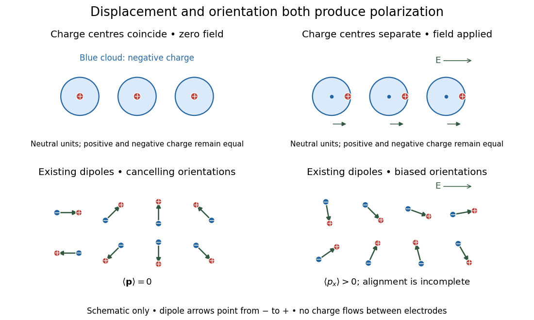
Two microscopic routes to electric polarization
. Original schematic: upper panels show coincident charge centres becoming separated; lower panels show existing electric dipoles changing from cancelling orientations to a biased distribution with incomplete alignment. Arrows run from negative to positive electric charge. Positions, displacements and orientations are illustrative, not measurements or a simulation of a particular substance. Details.Compare two initially identical parallel-plate capacitors with plate area , fixed gap , vacuum capacitance , and initial electric potential difference . Completely fill both gaps with the same uniform linear dielectric of static relative permittivity , neglecting the fringing field of a capacitor. Keep one connected to an ideal voltage source and isolate the other. The geometric capacitance becomes in both cases; the electrical constraint determines what else changes.[ref]
8.4 Capacitor with a Dielectric. §8.4, Figure 8.17 and equation (8.11): isolated capacitor, unchanged free plate charge and increased capacitance
Write , and . Applying , and the capacitor energy formula gives the complete comparison:Thus the statement that a dielectric reduces the electric field needs the fixed-free-charge condition. With fixed electric potential difference, the voltage source supplies additional free plate electric charge, maintaining despite the new bound electric charges.
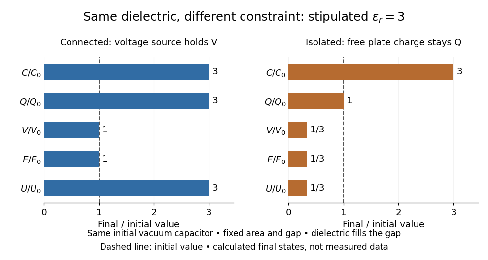
Dielectric capacitor response at fixed voltage and fixed charge
. Original normalized comparison for the stipulated model : every ratio is relative to the same initially charged vacuum capacitor. The dashed line marks the initial value. The bars show final values, not a time history or measured data. Plate geometry is unchanged and the dielectric completely fills the gap. Details.For the stipulated example, the voltage source supplies . At constant , its delivered electrical work is , whereas the increase in capacitor energy is . In an ideal reversible quasistatic insertion, the remaining is mechanical work delivered by the assembly, as accounted for in fixed-voltage capacitor energy balance. For the isolated assembly, capacitor energy falls from to , allowing of mechanical work in the same ideal limit. Actual losses reduce recoverable work; energy increases in the connected case do not arise from the dielectric supplying free energy.
An electrical insulator has sufficiently small transport of electric charge for its operating conditions. Insulation is a practical requirement involving electric potential difference, temperature, geometry and duration, rather than a universal claim of zero electrical conductivity. Electric polarization can be substantial in an electrical insulator; dielectric breakdown can end the insulating regime.
For an idealized uniform slab with small constant electrical conductivity , the Ohmic conductor model predicts leakage electrical resistance in parallel with capacitance . An isolated capacitor then hasThis is a derived model of slow discharge, not an assertion that every leakage mechanism obeys Ohm's law. Its time scale matches charge relaxation. The fixed-charge comparison in dielectric capacitor response needs an observation time short compared with , but long enough for electric polarization to settle. During a maintained voltage, leakage consumes power as Joule heating; delayed electric polarization can add dielectric loss under changing electric fields.[ref]
Materials Measurement: Dielectric Materials. Overview: real and imaginary permittivity, storage and dissipated loss
Large relative permittivity alone does not rule out either mechanism.[ref]
8.5 Molecular Model of a Dielectric. §8.5, paragraph following Table 8.1: high dielectric constant does not ensure a good insulator; mobile ions permit conduction
A correlated transition-metal compound whose lowest charge excitation primarily transfers an electron between a ligand orbital and a metal orbital. Its gap is controlled by charge-transfer and Coulomb energies rather than a weakly interacting single-band picture alone. Many cuprate parent compounds are usefully described this way. This distinguishes the orbital character of the low-energy excitation from an idealized single-band Mott insulator.
Dielectric breakdown is failure of an insulating regime under a sufficiently strong electric field, allowing substantial electric current through the material. For example, an electron freed from a chemical atom or molecule can become a mobile charge carrier. The small-field linear electric susceptibility model does not describe this conducting state.[ref]
8.5 Molecular Model of a Dielectric. §8.5, dielectric breakdown paragraph immediately before the definition of dielectric strength
For an ideal uniform dielectric between large parallel plates, . A prescribed breakdown field therefore limits charge independently of plate separation. Voltage capacity still grows with separation. This ideal result neglects field enhancement near edges and any dependence of the breakdown field on gap geometry or environmental conditions.
Dielectric strength characterizes the electric field at dielectric breakdown under specified test conditions. In an ideal uniform gap, it sets a voltage scale .[ref]
8.5 Molecular Model of a Dielectric. §8.5: dielectric strength definition and voltage limit for a specified plate separation
The parallel-plate capacitor model consequently gives the stored energy density scaleThis is a model scale, not an operating rating: fringing field of a capacitor make local electric fields differ from , while leakage and dielectric loss spend some supplied energy as heat. Comparing usable capacitor energy therefore requires insulation and breakdown performance as well as permittivity.For harmonic electric fields with time convention , write for their complex amplitudes, where is angular frequency. The real part describes the in-phase electric displacement field; the minus imaginary part describes the loss component. The sign reverses with the opposite time convention. Complex permittivity can also be a tensor in a linear anisotropic dielectric.
With phasor convention , the Ampere-Maxwell law in a scalar conductor reads . Factoring gives the displayed effective relative complex permittivity. Its positive imaginary conductive term expresses loss in this convention; the sign reverses for . This combines conduction and displacement currents for the same field and must not be confused with the material's loss-free relative permittivity alone.
Conversion of electrical energy into heat in a dielectric driven by an electric field. In the stated harmonic convention, a passive scalar response has for positive angular frequency. A dielectric capacitance measurement measures a dissipative component as well as capacitance; leakage from electrical conductivity can contribute to the inferred loss.
For a capacitor represented by ideal capacitance and series electrical resistance , the complex impedance is . The ratio of its dissipative part to the magnitude of its reactive part is . This dimensionless ratio characterizes loss at a specified frequency; equivalent parallel parameters generally differ from the series parameters.
Delayed adjustment of electric polarization after a change in electric field. A simple illustrative model lets the slowly adjusting part obey , with a positive response time . A harmonic electric field then gives a contribution to complex permittivity divided by vacuum permittivity. This model is an assumption, not a claim that all dielectrics have one response time.
The motivating observation is that inserting an insulating material between fixed capacitor plates increases its capacitance. [ref]
https://www.feynmanlectures.caltech.edu/II_10.html#Ch10-S1. Feynman, Leighton and Sands, II.10–1, opening paragraphs: observed increase in capacitance with an inserted insulator
. To investigate this response, use two flat parallel metal electrodes with measured overlapping area and separation , a uniform specimen filling the gap, and an instrument that measures electrical impedance. Record the capacitance with and without the specimen at the same small applied electric potential difference, frequency and temperature, after capacitance measurement calibration. An increase in corrected capacitance indicates a larger permittivity, provided the geometry is unchanged. A guard electrode reduces the contribution of the fringing field of a capacitor. [ref].For negligible dielectric loss in the parallel-plate capacitor approximation,An air reference approximates ; it is not an exact vacuum reference. For the following synthetic example, stipulate , and the rounded vacuum permittivity . Then in this model, and relative permittivity four gives . A residual parallel capacitance of would make an uncorrected sample/reference ratio , rather than four. This additive error does not cancel in a ratio.
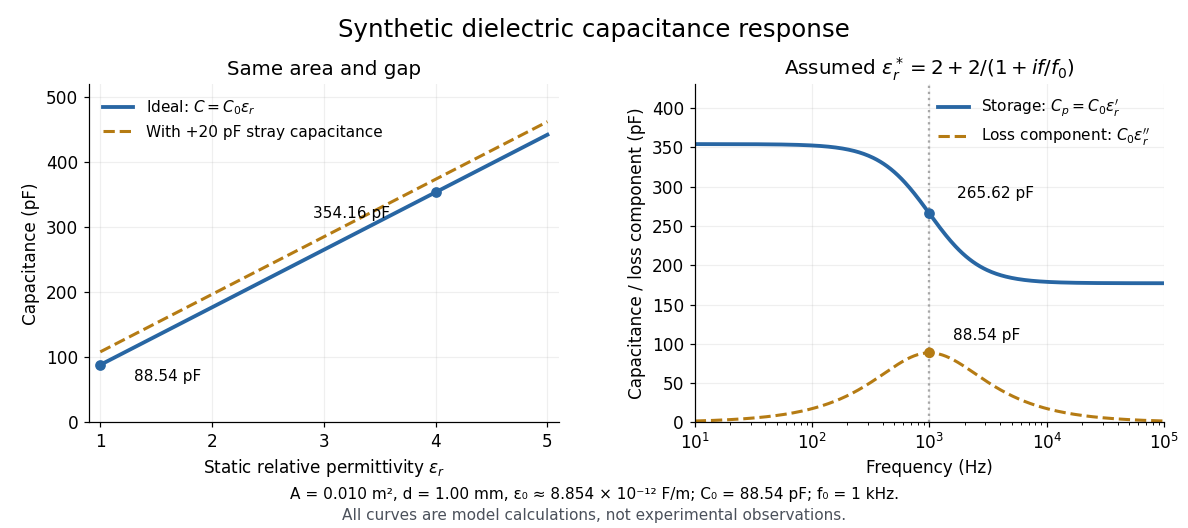
At nonzero frequency , measure both magnitude and phase of the electric current relative to the applied electric potential difference. Define , where is electrical impedance. For the stated complex permittivity convention, the ideal uniform specimen givesThus a parallel capacitor and electrical conductance describe the readout at that frequency; a single scalar capacitance cannot describe both components. The diagram's assumed dielectric relaxation gives and at . These are model predictions, not observations.
Repeat the reference measurement after removing the specimen and vary the small applied electric potential difference to test drift and linearity. Record specimen thickness, electrode area, contact conditions, frequency and temperature. Air gaps act as additional layers in series and can lower inferred relative permittivity; roughness, uncertain thickness and the fringing field of a capacitor limit the geometric formula. At sufficiently high frequency, the fixture itself changes the electromagnetic field, so low-frequency guarding and a lumped capacitor model require reassessment. [ref].
Characterize the instrument and fixture before inferring permittivity: use the prescribed open and short measurements to compensate residual parallel response and series electrical impedance, and check a known reference capacitor or the required load standard. Keep cables and electrode geometry reproducible. An open fixture measurement is distinct from the empty-gap reference capacitor; blindly subtracting its entire capacitance would remove the desired reference signal. Compensation cannot determine an incorrectly measured specimen thickness or eliminate all specimen-dependent fringing field of a capacitor errors. [ref].
Southern Methodist University's teaching lab, Introduction to the Parallel Plate Capacitor Lab, makes the response tangible with a capacitor assembled from aluminium foil, paper and taped wire contacts. Its instructions specify approximately foil rectangles, aligned with the paper completely separating them. A multimeter in capacitance mode supplies the readout; a ruler measures plate dimensions and a micrometer measures specimen thickness. The lab replaces the paper with other sheets, including cardstock, plastic wrap and wax paper. It asks students to keep foil area and alignment consistent, measure thickness at several positions, estimate thickness uncertainty, and wait for the capacitance reading to stabilize. These are published preparation and measurement instructions, not measured results reported here.[ref]
Introduction to the Parallel Plate Capacitor Lab. Experiments 1–2, Equipment You Will Be Using, and final construction and dielectric-study instructions
The inference uses each specimen's own thickness , not just a comparison of raw meter readings. With corrected capacitance and overlapping area , the ideal estimate is . A thicker sheet can give a smaller capacitance despite larger relative permittivity. This is why changing material while letting the plate gap change does not isolate electric susceptibility by itself.
Useful additional controls are to keep leads in the same positions, use capacitance measurement calibration, repeat one sheet after the others to check drift, and repeat the assembly to assess contact reproducibility. An air-gap reference must have known spacers maintaining the same separation; removing a supporting sheet and letting the foil touch is not such a reference. Record the instrument's test frequency and measurement mode when available. A capacitance display alone does not establish negligible dielectric loss or a strictly static permittivity. These are proposed controls extending the published teaching instructions.
Air gaps produce a particularly revealing systematic error. Suppose a uniform sheet of thickness and relative permittivity is separated from the electrodes by air layers of total thickness . Approximate air permittivity by vacuum permittivity, neglect the fringing field of a capacitor and use the same area in each layer. The common normal electric displacement field has magnitude , so integrating the electric field through the layers givesIf the analyst inserts the sheet thickness alone into the ideal filled-gap formula, the inferred value isFor the stipulated model and , this gives , not three. These values are calculated examples, not measured sheet properties. If total plate separation is used instead, the effective estimate is ; it still mixes the sheet and the air. Thus measuring a thickness accurately cannot compensate for an unrecognized layer.
The fringing field of a capacitor and additive lead capacitance further limit a foil measurement. Keep lateral plate dimensions large relative to separation, and use a guard electrode of a capacitor in a suitable fixture for more demanding work.[ref]
Materials Measurement: Dielectric Materials. Solution: guarded three-electrode fixture, fringe capacitance, specimen flatness and air gaps
A family of thickness measurements can help distinguish material response from an additive offset, but air gaps can vary with the assembly. A large, repeatable reading supports a capacitance change; extracting a material electric susceptibility requires the geometry, gaps, instrument response and dielectric loss assumptions to survive these checks. No measured relative permittivity is claimed for any of the lab's sheets.Vacuum permittivity is the electromagnetic constant in Coulomb's law and the Vacuum Maxwell equations. In classical vacuum, and the electric displacement field is . A material's permittivity includes its electric polarization response; vacuum permittivity supplies the common reference, not a separate adjustable material property. Its SI unit is farad per metre.
For elementary calculations, vacuum permittivity is approximately . This is a deliberately rounded value, not an exact decimal or a statement of current measurement precision.[ref]
Fundamental Physical Constants — Complete Listing by National Institute of Standards and Technology and others. 2022 CODATA adjustment, vacuum electric permittivity row: value and nonzero standard uncertainty
It sets the scale in Coulomb's law, for two stationary point electric charges with separation length in vacuum, and therefore enters the reference capacitance of a parallel-plate capacitor.Since the revised SI took effect on 20 May 2019, the numerical value of vacuum permittivity in SI units is determined experimentally, rather than fixed exactly by the unit definitions. The numerical values of the elementary charge , Planck constant and speed of light are fixed exactly. The fine-structure constant is measured, andwhere is vacuum permeability. Consequently vacuum permittivity and vacuum permeability have experimental uncertainty, while their product is exact in SI units because is exact. This is a change in metrological status, not a new material dependence of vacuum permittivity.[ref]
Articles by others on the same topic



Permittivity is a fundamental physical property of materials that quantifies their ability to permit electric field lines to pass through them. It is a measure of how much electric field (E) is induced in a medium when an electric charge is present. In other words, permittivity indicates how much electric field is "allowed" in a given material. The official unit of permittivity in the International System of Units (SI) is farads per meter (F/m).