In the kinematic approximation, the face-centered cubic lattice contributes only reflections with all even or all odd. Viewing along selects the zero-order zone , so the nonzero allowed spots within the cutoff are , with the transmitted beam at the centre. The nearest-neighbour separation is in the crystallographic reciprocal-distance convention, or in the angular-wavevector convention. No matrix lattice parameter is supplied, so a numerical matrix spacing would require extra data.
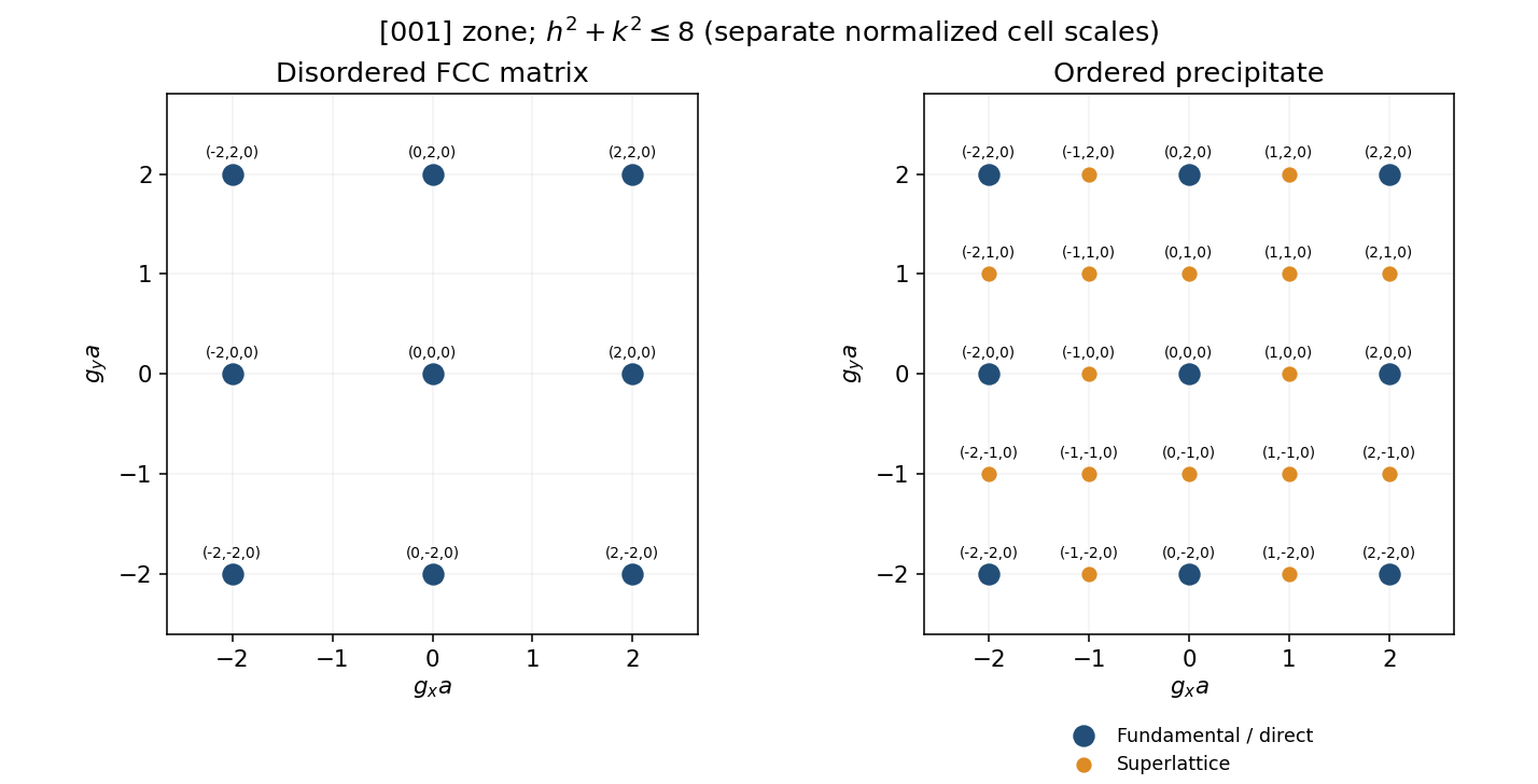
Calculated zero-order diffraction spots before and after chemical ordering
. Original kinematic spot diagrams with reciprocal coordinates normalized by the relevant cubic cell edge. The right panel shows additional superlattice positions; actual intensity also depends on thickness, excitation and scattering factors. Details.
For the L12 structure, the crystal basis structure factor isEqual parity of makes all three phase factors , henceThe electron scattering factors are evaluated at the reflection's scattering vector.
For mixed parity, one of the three pair sums is even and two are odd. Thus their phase factors sum to , givingThese superlattice reflections reveal chemical ordering. Their kinematic intensity is proportional to , and vanishes in the hypothetical limit of equal species scattering factors.
Keep the matrix spots and add precipitate reflections at all integer with . Even-even spots are fundamental; every other allowed position in this zone is a superlattice reflection. The added positions are and their symmetry-related signs. Each position actually denotes the corresponding signed index pair, not one radial ring. The precipitate grid spacing is ; the nearest fundamental separation is . If matrix and precipitates are coherent and similarly oriented, their fundamental spots approximately coincide, with finite mismatch potentially giving splitting or broadening. The sketch assumes common orientation, small strain, appreciable sampled precipitate volume and predominantly single scattering; electron diffraction can have dynamical intensity effects.
Choose an objective aperture around a precipitate superlattice reflection, such as , which is absent from the disordered aluminium matrix. The selected beam then makes precipitates bright in dark-field transmission electron microscopy, while the matrix gives little intensity in that beam. Tilt the grain to place the chosen reflection close to its Bragg diffraction condition and preferably approach a two-beam geometry. This reduces excitation error and can increase precipitate brightness; the exact maximum also depends on foil thickness, strain and dynamical scattering. Selecting a shared fundamental reflection would give much poorer chemical-order selectivity.
Articles by others on the same topic
There are currently no matching articles.