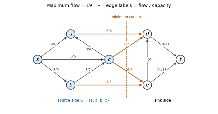
Reading the arrows directly from the original PDF gives, in particular, and . Starting from zero flow, use the following augmenting paths and bottlenecks, in order:
- : .
- : .
- : .
- : .
- : .
Each path is available in the current residual network. The resulting nonzero edge flows areThe flows on and are zero. Capacity constraints and flow conservation hold at each interior vertex; net source outflow is .
Take . Its outgoing edges are , , , , with total capacity . Thus the matching flow and cut of a flow network certificates giveThese are also exactly the source-reachable vertices in the final residual network. The original drawing below labels each edge by flow/capacity; the highlighted edges realise the minimum cut of a flow network.
Articles by others on the same topic
There are currently no matching articles.