Treat the specified particles only as rigid geometric shadowing objects; no biological preparation or interpretation is needed. Their projected shapes are rounded-ended rods with straight central length and cap radius . Normal, collimated evaporation deposits metal in the gaps between projected particle footprints, leaving isolated small islands after mask removal, rather than a metal replica of each rod.
One concrete dense parallel packing has center translationsAdjacent rounded ends then touch at triangular arrangements. The open regions are small curvilinear triangular gaps near those ends. This is a specified geometrical packing for the sketch; the words close-packed do not uniquely prescribe the domain orientation or registry of all real sheets.
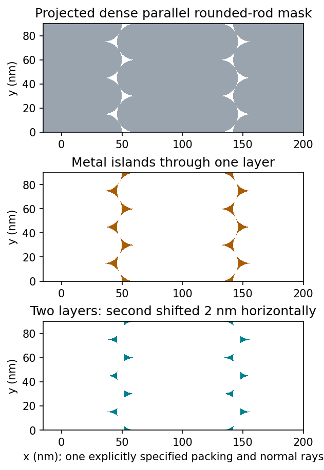
Original geometric calculation of rounded-rod shadow masks, deposited islands and the effect of shifting a second layer; no source illustration is reproduced
. Details. 
Particle size and shape distributions change the gap size and spacing. Misorientation, missing particles, boundaries between ordered domains, overlaps, incomplete coverage and drying-induced cracks interrupt long-range order. Substrate roughness and uneven adhesion distort the arrangement. A finite source angle produces deposition shadowing and penumbra; surface diffusion, island nucleation and increasing film thickness can broaden or merge deposited regions. These are generic geometry and materials effects, not assumptions about a biological assembly mechanism.
Let and be the open projected regions in the two layers. For normal, collimated rays, the transmitted opening is the intersectionAn upper particle blocks any lower-layer gap beneath its footprint. A translated layer can therefore reduce island size, suppress some islands or close the holes completely. If the projected openings coincide, an ideally registered second layer need not change the pattern at all. A rotated or differently registered layer can create a larger superperiod or a less regular pattern.
The additional height also increases the separation between some blocking edges and the substrate, making a finite angular source distribution more important. Deposition angle and layer separation then enter the projected aperture geometry. No unique double-layer pattern follows without specifying registry, orientation and source direction; the figure illustrates aligned and shifted possibilities instead of treating one as inevitable.
Articles by others on the same topic
There are currently no matching articles.