Treat the specified particles only as rigid geometric shadowing objects; no biological preparation or interpretation is needed. Their projected shapes are rounded-ended rods with straight central length and cap radius . Normal, collimated evaporation deposits metal in the gaps between projected particle footprints, leaving isolated small islands after mask removal, rather than a metal replica of each rod.
One concrete dense parallel packing has center translationsAdjacent rounded ends then touch at triangular arrangements. The open regions are small curvilinear triangular gaps near those ends. This is a specified geometrical packing for the sketch; the words close-packed do not uniquely prescribe the domain orientation or registry of all real sheets.
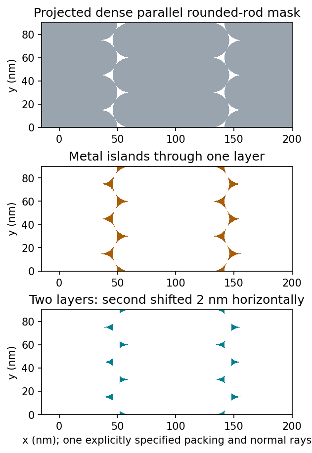
Original geometric calculation of rounded-rod shadow masks, deposited islands and the effect of shifting a second layer; no source illustration is reproduced
. Details. 
Particle size and shape distributions change the gap size and spacing. Misorientation, missing particles, boundaries between ordered domains, overlaps, incomplete coverage and drying-induced cracks interrupt long-range order. Substrate roughness and uneven adhesion distort the arrangement. A finite source angle produces deposition shadowing and penumbra; surface diffusion, island nucleation and increasing film thickness can broaden or merge deposited regions. These are generic geometry and materials effects, not assumptions about a biological assembly mechanism.
Let and be the open projected regions in the two layers. For normal, collimated rays, the transmitted opening is the intersectionAn upper particle blocks any lower-layer gap beneath its footprint. A translated layer can therefore reduce island size, suppress some islands or close the holes completely. If the projected openings coincide, an ideally registered second layer need not change the pattern at all. A rotated or differently registered layer can create a larger superperiod or a less regular pattern.
The additional height also increases the separation between some blocking edges and the substrate, making a finite angular source distribution more important. Deposition angle and layer separation then enter the projected aperture geometry. No unique double-layer pattern follows without specifying registry, orientation and source direction; the figure illustrates aligned and shifted possibilities instead of treating one as inevitable.
Expect appreciable but nonuniform sidewall coverage, rounded upper edges and possible narrowing near the opening mouth. In sputtering, gas collisions and the extended source distribute arriving material over a broader range of directions than simple high-vacuum evaporation. At the specified pressure, the extent of that redistribution also depends on source-to-substrate distance and particle energies; pressure alone does not determine a unique sidewall thickness.
The top surfaces receive the nominal film. Oblique rays coat accessible walls, while the tall opening shadows some directions from its lower portions. Growth at the mouth can further shadow the floor or form an overhang. The sidewall film is therefore neither guaranteed zero nor guaranteed as thick as the horizontal film. This step coverage is generally unfavorable for clean lift-off process if it connects the film on the resist to the film on the substrate.
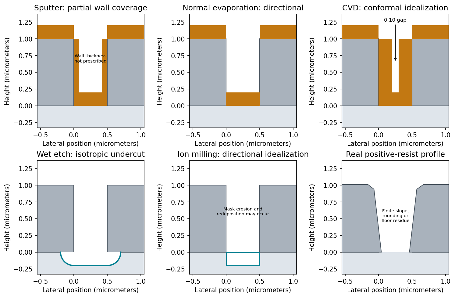
Original schematic process outcomes for deposition and etching through a resist opening; sidewall coverage and erosion are qualitative where not fixed by the question
. Details. 
Normal evaporative deposition gives approximately horizontal films on the resist tops and exposed substrate, with little coating of vertical walls. A small distant electron-beam-heated source in high vacuum gives nearly line-of-sight arrival. Near-normal rays reach the opening floor, while vertical walls present almost no projected area.
The floor film and top film can remain disconnected, which helps a later lift-off process. A finite source size, tilted incidence, scattering or sample rotation changes that idealization and may coat one wall or shadow part of the floor. The stated thickness is well below the resist height, but this alone does not guarantee a clean break at every real edge.
A compatible, reaction-limited chemical vapor deposition process can give nearly conformal coverage of tops, sidewalls and floor. Gas-phase precursors reach recessed surfaces and react there; the coating is not restricted to the line of sight of a solid source. The result is a continuous film over the resist pattern, which is unfavorable for ordinary lift-off process.
If each wall receives the same coating as a horizontal surface, the nominal gap narrows toThat numerical result is the conformal idealization. Precursor depletion or rapid surface reaction can instead give poorer bottom coverage or premature closure near the mouth. Actual silver chemistry and deposition temperature must also be compatible with the resist; a process that decomposes the resist does not preserve the illustrated mask.
An approximately isotropic wet etch produces lateral undercut as well as downward removal. In the hydrofluoric acid and nitric acid mixture, oxidation of silicon and dissolution of the oxidized material cooperate. This is not the strongly crystal-anisotropic KOH-type picture.
If the exposed horizontal surface recedes about and the local rate is isotropic, the etch front advances a comparable distance beneath each resist edge. A section through the front has rounded corners, and the silicon support under the mask narrows. The mouth can consequently widen laterally by roughly in total at the original surface level. The precise contour depends on transport, chemistry and mask integrity; the diagram represents the isotropic geometrical limit.
Near-normal ion milling preferentially removes exposed horizontal silicon and gives a more directional trench with much less lateral undercut. Energetic argon ions eject surface atoms by momentum transfer. The resist blocks direct trajectories to the protected regions.
After about removal of exposed silicon, expect an approximately flat recessed floor and steep transitions near the mask edges. The mask is also sputtered: finite etch selectivity, angular yield variations, mask-edge faceting and redeposition can produce sloped walls, fences or residue. No resist erosion depth can be deduced without its sputter rate. Thus a perfectly unchanged rectangular mask is only the ideal sketch.
A real positive photoresist pattern usually has finite edge slope and rounding rather than mathematically sharp vertical steps. The optical aerial image and finite resist contrast give a graded exposure boundary. Absorption through the film, focus, reflections from silicon and development kinetics can make the opening narrower or wider at different heights.
Incomplete development can leave residual material at the floor; standing-wave exposure can cause sidewall ripples, and substrate-related chemistry can produce footing. Bake history and developer transport can modify corners and line width. An undercut can be engineered with a suitable resist stack, but it is not an automatic consequence of ordinary positive-tone processing. The final profile must therefore be measured rather than inferred solely from the mask artwork.
Articles by others on the same topic
There are currently no matching articles.