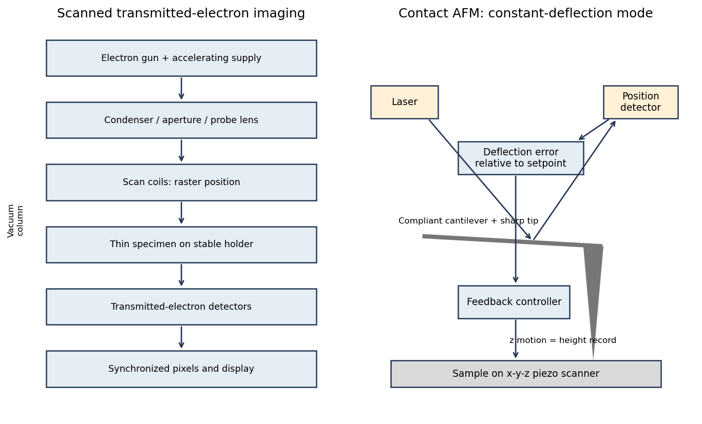
In contact-mode atomic force microscopy, a sharp tip on a compliant cantilever remains in contact with the surface while a feedback loop controls its normal deflection. A laser reflected from the cantilever onto a position-sensitive detector converts bending into an electrical error signal. With calibrated deflection and stiffness , the normal force is approximately under the stated contact convention.
A piezoelectric scanner raster-scans the sample or tip. The controller adjusts vertical position to maintain the chosen deflection setpoint; that vertical displacement is recorded as topography. The right panel of the microscopy diagram identifies tip, cantilever, optical deflection readout, controller and vertical actuator.

Articles by others on the same topic
There are currently no matching articles.