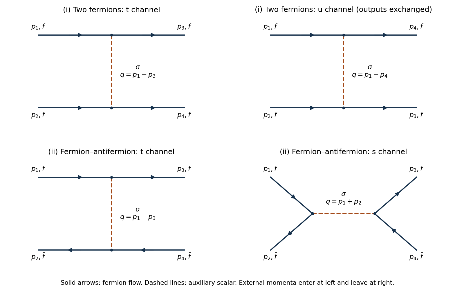
Original tree diagrams with external momentum labels and fermion-flow arrows. The upper row gives two-fermion t and u exchange; the lower row gives fermion–antifermion t exchange and s annihilation. Dashed lines denote the auxiliary scalar.
Details. 
Label the incoming fermion momenta and outgoing fermion momenta , with . There are two tree-level Feynman diagrams: the channel connects to and to , with exchanged momentum ; the channel connects to and to , with . Both internal lines are auxiliary-field propagators. The upper row in the figure gives these labelled connections; the outgoing labels are exchanged in its second panel to avoid a visually unnecessary crossing.
Each tree-level Feynman diagram contains two factors and one factor , giving . The exchange of the two identical outgoing fermions gives the relative fermionic sign. Up to a common external-state phase, the corresponding scattering amplitude isThere is no annihilation channel: both incoming particles carry the same fermion number, whereas a interaction vertex couples one fermion to one antiparticle when both are incoming.
Use incoming fermion and antiparticle , outgoing fermion and antiparticle . The two tree-level Feynman diagrams are the channel, with , and the channel, with . They occupy the lower row of the figure. In the channel the fermion flow follows and ; in the channel it follows at the incoming interaction vertex and at the outgoing interaction vertex.
The two contractions again have a relative fermionic sign. With the same harmless common-phase convention as i, their sum isThe auxiliary-field propagator is the same constant in both channels. There is no channel preserving the external fermion number assignments.
Articles by others on the same topic
There are currently no matching articles.