In a least-significant-first bit-serial comparator, the new pair has higher significance than every pair already processed. Equal new bits preserve the earlier result; unequal new bits decide the new result regardless of earlier bits. Use a left fold starting at equality:
type Bit = Int
data LEG = Lt | Eq | Gt deriving (Eq, Show)

step :: LEG -> (Bit,Bit) -> LEG
step old (a,b)
  | a < b = Lt
  | a > b = Gt
  | otherwise = old

compare :: [Bit] -> [Bit] -> LEG
compare as bs = foldl step Eq (pairs as bs)
  where
    pairs [] [] = []
    pairs (a:as) [] = (a,0) : pairs as []
    pairs [] (b:bs) = (0,b) : pairs [] bs
    pairs (a:as) (b:bs) = (a,b) : pairs as bs
Inputs have the precondition that each
Bit is 0 or 1. Equal-length inputs are the physical circuit case; pairs also gives a defined unsigned meaning to unequal lengths by padding the shorter input with high-order zeros. Ordinary zip would silently discard significant unmatched bits.After pairs the fold accumulator compares and . Equal new bits add the same amount. If , the new difference has magnitude , exceeding the maximum magnitude of the earlier difference. This proves the accumulator invariant and givesFor the four pairs in the source, the states are
Lt, Gt, Gt, Lt, so the final result compares correctly.Use two stored bits with symmetric meanings:Swapping the two numbers interchanges and and fixes equality. Decode the outputs byThus only the equality output needs extra logic gates, namely two inversions and an AND gate, or a NOR gate. Code
11 is unused. Initialize both D flip-flops to zero before a new pair of numbers so the starting state is Eq. In normal operation only the three valid codes are reachable.The finite-state machine retains its state on input
00 or 11, moves to Lt on 01, and moves to Gt on 10. Here each input label is the pair ab, not a pair of outputs. The following state-transition diagram shows every valid-state transition; a diagonal input is stronger than all previous comparison history because it arrives at a more significant position.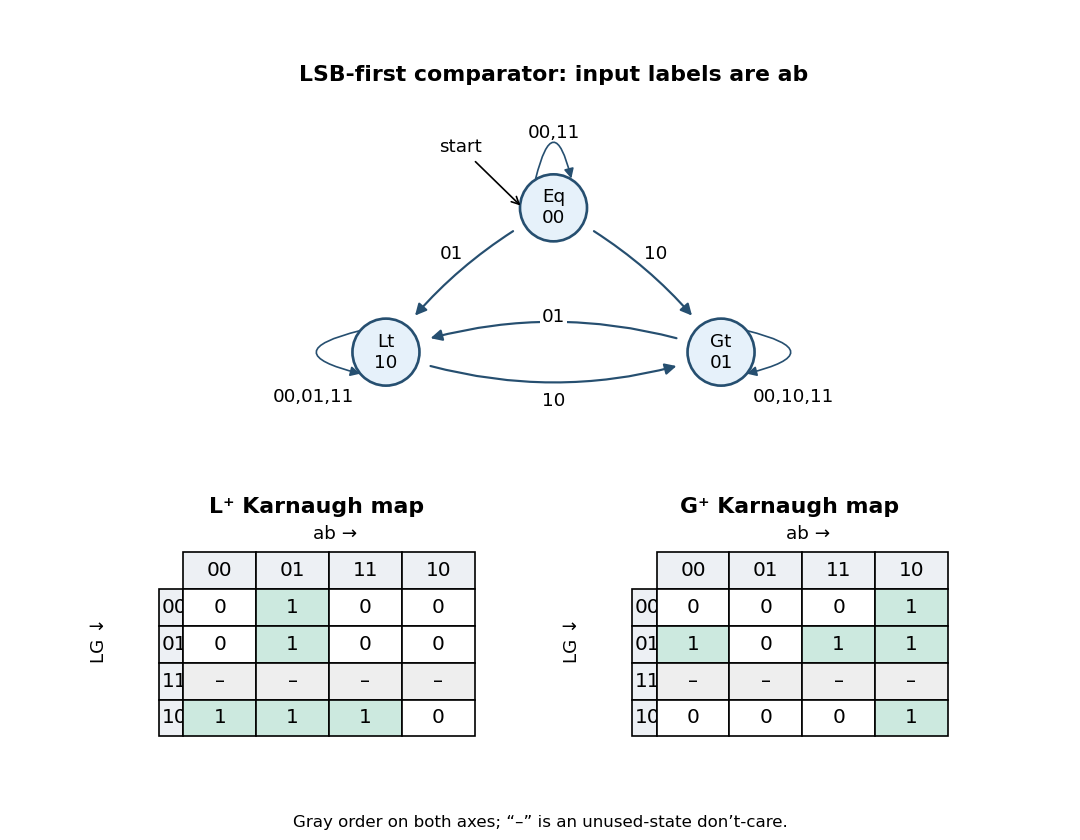
Least-significant-first comparator transitions and Karnaugh maps
. Details. 
Equivalently the complete transition rule isThe state-transition diagram starts at
Eq, representing the comparison of two empty, hence zero-valued, bit strings.Let denote the state after the next active clock edge. In the truth table, an entry is the two-bit next-state code, and
– marks a don't-care value for the unused current state 11:| Current | ||||
|---|---|---|---|---|
(Eq) | ||||
(Lt) | ||||
(Gt) | ||||
| (unused) |
For each input column,
01 forces , 10 forces , and the two equal-input columns copy the current code. Thus this compact truth table specifies all twelve valid combinations of state and input, or twenty-four individual next-state bits:Arrange each four-variable Karnaugh map in Gray code order down the rows and across the columns. For the row strings are
0100, 0100, ----, 1110; for they are 0001, 1011, ----, 0001. The maps are drawn alongside the state-transition diagram above.In the map, group the whole
ab=01 column to obtain . Group rows 11,10 with columns 00,01 to obtain . Group those same rows with columns 01,11 to obtain . The unused-state row permits these larger groups. Symmetrically, in the map group column ab=10, rows 01,11 with columns 11,10, and those same rows with columns 10,00 (wrapping around the map). This givesThese expressions drive the D inputs of the two D flip-flops. With , both copy their stored bit. With , they force Lt; with , they force Gt. The equations also specify a harmless extension at unused code 11: equal inputs retain it and unequal inputs recover to a valid comparison state. Correct reset is still required. This extension was chosen using don't-cares; the circuit is not claimed to recover from every invalid state without reset. Articles by others on the same topic
There are currently no matching articles.