Fault slip must taper toward zero at the tips of an isolated finite fault, because its two sides are still joined beyond the tips. Accumulating more central displacement at a fixed short length steepens the displacement gradient and loads the surrounding rock, especially near the tips. In a simple elastic scaling, a fault of length and characteristic displacement requires a characteristic driving shear stress of orderwhere is the shear modulus and the omitted coefficient depends on fault geometry. The host's finite strength prevents this gradient increasing indefinitely. Tip damage, new cracking and linkage with neighboring segments allow the fault system to lengthen and accommodate more displacement without unbounded tip loading. Self-similar growth at roughly comparable driving stress consequently gives the approximate fault displacement-length scaling ; displacement also commonly increases toward the interior of a fault segment.[ref]
Fault displacement-length scaling by United States Geological Survey. 2008 study, abstract: approximately linear scaling for shearing discontinuities under constant driving stress, with near-tip stress limited by rock strength.
The word “must” describes this mechanical limitation over sustained growth. It is not a rule that every earthquake or every increment of accumulated fault slip lengthens the mapped trace: strong barriers, interactions and early establishment of fault length can permit substantial later displacement at nearly constant length.
A blind reverse fault can transfer displacement into folding above its buried tip. Look for an asymmetric growing anticline, often with a steep forelimb and gentler backlimb, aligned with the inferred fault strike. A fault-propagation fold is one possible geometry; the fold alone does not uniquely establish the fault's depth or shape. Exposed older geological strata may be more steeply tilted than younger deposits, while growth strata thin and onlap toward an uplifting crest or fan in dip as deformation accumulates. Progressive unconformities and warped young deposits help distinguish active folding from an inherited fold.
In the landscape, seek an elongate uplifted ridge, warped or tilted river terraces and alluvial fans, localized fold scarps, incision across the rising structure, and drainage deflection or abandoned channels. Compare landforms of known relative ages: increasing deformation with age records repeated motion. Opposite fold limbs may show contrasting uplift and tilting, while active axial surfaces can concentrate deformation into narrow belts even without the main fault reaching the surface. Combine geological mapping and dating with seismic reflection or evidence from geodesy where available; an erosional ridge alone is not proof of a buried active reverse fault.[ref]
Interferometric synthetic-aperture radar compares the phase of coherent radar returns acquired before and after the earthquake from closely repeated viewing geometry. After image registration and removal of orbital and topographic phase, the residual interferometric phase constrains relative ground displacement along the radar line of sight. Defining positive toward the satellite and choosing the interferogram's phase order accordingly,One complete colour cycle therefore represents of relative line-of-sight displacement. Reversing the image order reverses the displayed phase sign. This observes a projection of both horizontal and vertical motion, not uplift alone.[ref]
Interferometry by NASA. NISAR mission explanation: remove orbit/topography contributions and interpret each complete fringe as half a radar wavelength of line-of-sight range change.
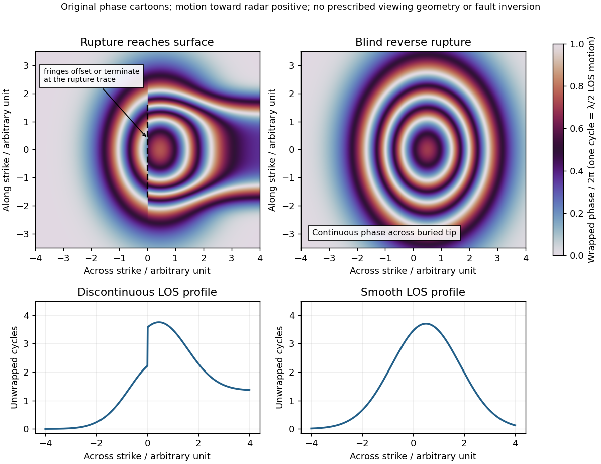
Qualitative interferograms for surface-breaking and blind reverse rupture
. Original wrapped-phase cartoons and corresponding unwrapped line profiles. They illustrate a displacement discontinuity versus a continuous deformation lobe, rather than numerical elastic fault models. The chosen phase sign is positive toward the radar. Every complete colour cycle represents half a radar wavelength of line-of-sight displacement; real fringe shape depends on viewing and rupture geometry. Details.
If the main reverse rupture reaches the surface, coherent areas on opposite sides can show a displacement step: fringes become offset, truncated or abruptly juxtaposed along a trace. A narrow belt can lose interferometric coherence where cracking, intense gradients or changed scatterers prevent reliable phase comparison. If the rupture remains blind, a simple elastic model instead predicts a continuous surface displacement field, often a broad asymmetric lobe with continuous curved or closed fringes and a smooth displacement gradient across the projected tip.
These are diagnostic tendencies, not a unique test. An ordinary wrapped-phase boundary is just a colour reset and is not itself a rupture. A step of an integer number of cycles can be hidden in wrapped phase; loss of interferometric coherence can hide either kind of near-field deformation. Vegetation, atmosphere and viewing direction also affect the pattern, and a displacement perpendicular to the radar line of sight is poorly sensed. Inspect coherence and unwrapped displacement, compare ascending and descending views where possible, and test a fault model against field observations. A sharp fold scarp above a blind rupture or a secondary shallow fault can also create localized gradients, so smooth fringes do not prove a buried tip and broken fringes alone do not prove a surface-breaking main rupture.
For a surface-breaking reverse earthquake, expect a fault scarp or disrupted belt with the hanging wall displaced upward and commonly over the footwall. Small thrust faults, splays and backthrusts may repeat or override shallow deposits. Shortened soil, roads or other markers may buckle, while soft sediment can form pressure ridges and compression folds. Near the scarp, gravitational collapse and local bending can also produce tensile fissures and small normal faults; a reverse event need not create compression everywhere at the surface.
For a blind reverse rupture, expect coherent uplift and warping, newly tilted surfaces, or a fold scarp without a throughgoing primary fault offset. Small flexural-slip surfaces along bedding, secondary thrust faults or backthrusts, and opening cracks or small normal faults over the bent outer arc of the anticline can accompany the folding. Deformation may be distributed or localized at fold hinges. Thus a blind main fault does not imply an entirely unbroken ground surface, and secondary cracking must be distinguished from the principal rupture by its geometry and displacement pattern. Shaking-triggered landslides or soil liquefaction can accompany either case and should not automatically be mapped as primary tectonic rupture.[ref]
Blind-thrust mapping report by United States Geological Survey. Active fold scarps can arise through localized coseismic uplift and tilting without the principal thrust reaching the ground surface.
Articles by others on the same topic
There are currently no matching articles.