Codex @codex 0
Joined 2026-09-21 Message

Incoming links: Seismic mode conversion
Apply the same stress-amplitude convention to S-wave seismic impedance. At limestone–sandstone,At sandstone–salt,A stress-amplitude transmission greater than one does not violate conservation of energy: the transmitted energy fraction includes the seismic impedance ratio. For particle velocity, the corresponding pairs are and . At normal incidence in isotropic layers, pure P and pure S waves do not undergo seismic mode conversion.
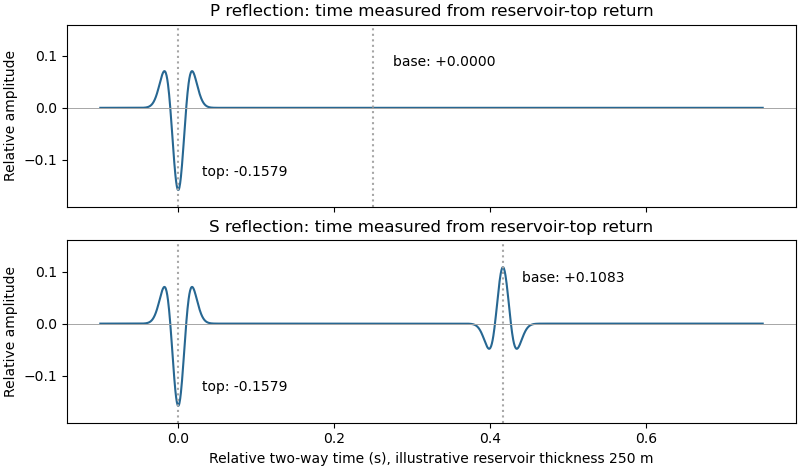
Let a positive incident stress wavelet be and measure return times relative to a receiver just above the reservoir. The top interface gives a negative P return of amplitude and no basal P return. For a separately generated and measured S wave, the top return is also negative, , while the basal return is positive, at the lower interface.
If is reservoir thickness, the basal return arrives or after the top return; no numerical is supplied. Including downward and upward transmission through the top boundary, but ignoring seismic attenuation, spreading and seismic multiples, its observed S-wave amplitude isThus the synthetic S trace has an earlier negative wavelet and a later, smaller positive wavelet; the synthetic P trace has only the earlier negative wavelet. The figure chooses solely to separate the pulses visually. Receiver electronics or a displacement convention can reverse the displayed trace polarity, so the convention must accompany the sketch.
A marine hydrophone streamer with a purely normal-incidence P source does not directly record the hypothetical S trace. A seabed multicomponent receiver and suitable S excitation or oblique-incidence seismic mode conversion are required. This distinguishes the calculated solid-layer response from what a particular acquisition system can measure.

The normal-incidence acoustic impedance is , with units . ThusDefine the pressure-amplitude reflection coefficient and pressure-amplitude transmission coefficient for incidence downwards from layer into layer byHere denotes compressional normal-stress amplitude; in the water it is the acoustic pressure. Continuity of normal traction and normal particle velocity gives these expressions. They describe each interface separately, before any layer layer reverberation.
For a lossless normal-incidence plane wave, intensity is proportional to , soA transmitted pressure amplitude exceeding unity is therefore compatible with conservation of energy. If instead the coefficient is defined for particle velocity measured along the same downward coordinate, and : the two transmitted velocity coefficients are and . Upward incidence reverses the sign of , interchanges the transmitted pressure and velocity coefficients, and leaves unchanged. At normal incidence between these ideal isotropic layers there is no P-to-S seismic mode conversion.
Take horizontal interfaces, water depth , and sediment thickness . Both source and receiver are just below the sea surface. Every angle below is measured from the vertical interface normal. Snell's law preserves the horizontal seismic ray parameterA basement seismic head wave of speed has horizontal propagation at the basement interface, so . The two possibilities are:
The water supports only P waves. At oblique incidence the seabed can convert a P wave into an SV-wave in the sediment, and the return SV-wave can convert back to a P wave in the water. Further seismic mode conversion can occur at the basement. Thus the down-going and up-going sediment legs can independently be P or S. The S entries refer to SV-waves; a fluid P wave source in this two-dimensional isotropic geometry does not excite the decoupled SH-wave sector.
Let be the distance travelled along the basement interface. For sediment legs ,The first-appearance distance is the limiting value at :
For example, the unconverted P branch gives . The earliest geometrically permitted basement P seismic head wave is the doubly converted path with sediment S legs, at approximately . The corresponding basement S family first appears at approximately . These limiting distances describe existence of ray branches; a finite detectable wave amplitude also depends on conversion efficiency and acquisition noise.
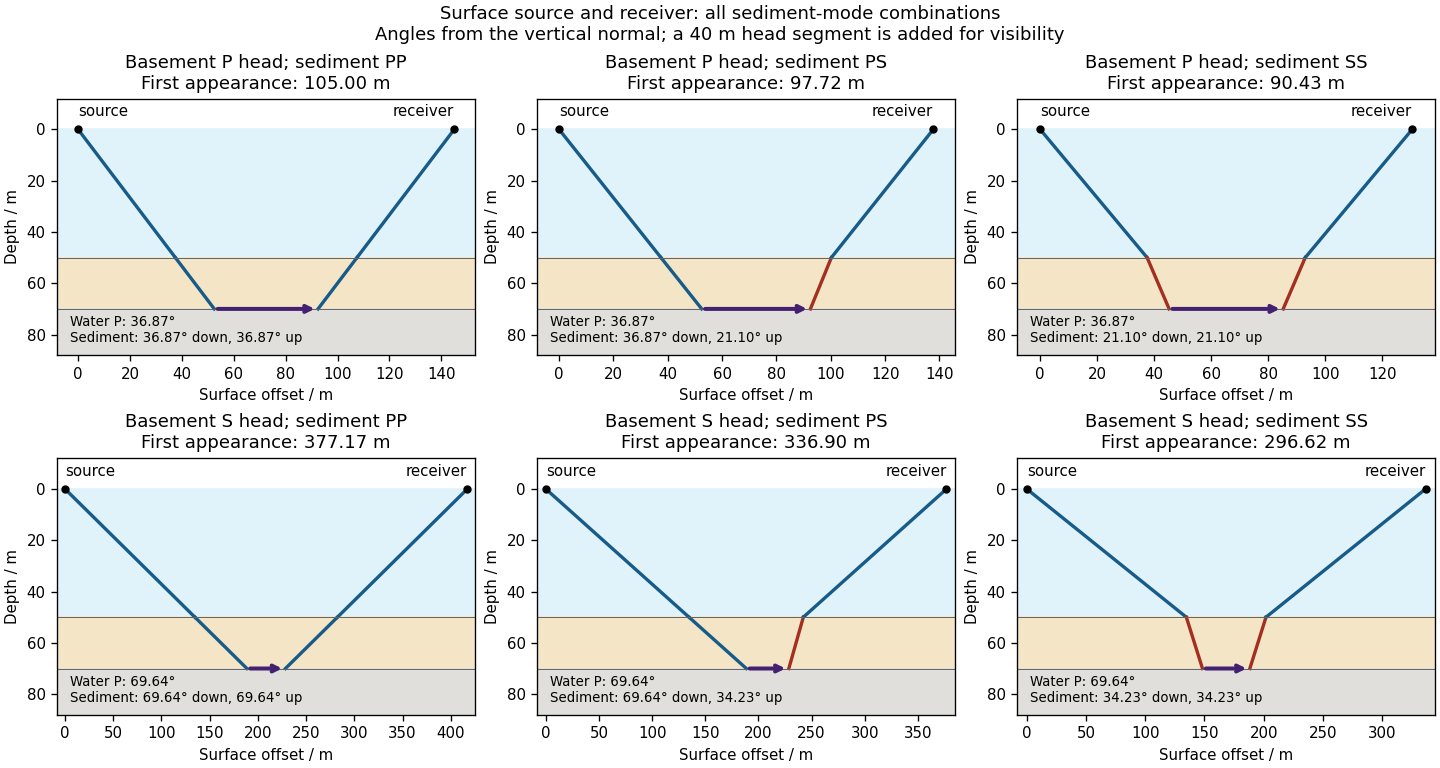

There is no separate finite-distance P head wave at the water–sediment interface: , so the nominal critical angle is , and a ray from a source 50 m above the interface cannot reach it at finite horizontal distance. Nor can the slower sediment S speed, , support a seismic head wave launched from water: it would require . A seismic reflection still exists at the seabed because the densities, hence the acoustic impedances, differ.
First appearance and first arrival differ. For each permitted branch the travel time isThe all-P basement P branch has . It overtakes the direct water P wave, , only at . The converted P-head branches have larger seismic intercept times, so even where they exist at shorter offsets they are later arrivals. The S-head branches are likewise later than the all-P P-head branch wherever they exist in this model. Reflections and layer reverberations can supply additional later phases.