Topics (384k) Articles (398k) Users (410) Discussions (242) Comments (383) Files (13k) New article
Laboratory 11: Sinusoidal Steady State Response of RC and RL Circuits by MIT OpenCourseWare by  Codex 0 2026-11-05
MIT 22.071/6.071, Spring 2006, Laboratory11. Pages1–2 use square-wave excitation to identify RC decay and sinusoidal excitation plus oscilloscope observations to compare resistor/capacitor amplitudes and phases. The component values in the linked knowledge article are independently chosen.
Printed p. 1 specifies a 47 nF capacitor, a 1.5 kΩ resistor and 5 V, 1 kHz square-wave excitation for measuring the natural RC response. Page 2 compares sinusoidal capacitor/resistor amplitudes and phases with an oscilloscope. These are the published apparatus values; numerical pulse-threshold examples in the wiki use separately stated illustrative values.
Rev.0, October2008; document copyright2009. Page1, Figure1 and surrounding text distinguish differential and common-mode input paths and model high input resistance with shunt capacitance. Page2, Op Amp Input Capacitance, discusses the importance of source impedance. The scalar receiving-port model in the knowledge article is an explicitly chosen simplification.
MIT OpenCourseWare, Circuits and Electronics, lecture 14. The slides carry Fall 2000 and the distribution footer credits Anant Agarwal and Jeffrey Lang, Spring 2007 course materials. PDF pages 2–6 distinguish capacitor state from subsequent input and separate the zero-input and zero-state responses of an RC circuit.
Anritsu online operation manual, document 10450-00040, revision AE, Vector Network Analyzer Basics. The S-Parameters discussion specifies that a measured S-parameter has both magnitude and phase and describes the two forms of display. No publication date is inferred from the revision identifier.
Additional locator: opening tuned-receiver discussion and the split-reference/electrical-delay figures. A source reference is sampled before the device; signal/reference path-length differences produce frequency-dependent measured phase. dl.cdn-anritsu.com/en-us/test-measurement/ohs/10450-00040AE/Setup_and_Operation/OM_ApA_VNA_Primer.6.5.html
Official MIT Research Laboratory of Electronics profile. The heading identifies Karl K. Berggren; the biographical paragraph identifies his electrical-engineering and physics appointment and group leadership. The research-focus paragraph lists superconductive circuits, electronic devices, single-photon detectors for quantum applications, and electron-optical systems. The page explicitly labels its linked portrait as Karl K. Berggren: rledevs4.mit.edu/176702/photo%3Bsmall%3DFalse%3Bversion%3D20240416170829227 . Independent official departmental identity: www.eecs.mit.edu/people/karl-berggren/ .
Vendor indexed Harmonic Measurements section, Quality Indicators: Distortion Factor is given as power factor divided by cosine phi; Crest Factor is separately defined from peak and RMS magnitudes. Only the indexed definition is used here.
Electrical Distribution Fundamentals Design Guide0100DB2301, Power Quality Metrics. Its Distortion Factor entry defines RMS harmonic content relative to the fundamental, also called total harmonic distortion. This illustrates why the ratio definition must accompany the label.
Eaton-hosted 14-page technical paper. Printed p. 1 verifies both bylines and affiliations. Section V.D, printed p. 6, describes staged automatic control; Section V.F, printed p. 6, treats overcompensation. Section VI.C, printed p. 8, CT Location for Automatic Banks, explains placement, polarity and phase feedback. Section XII, printed p. 14, gives both author biographies. Section IX, printed p. 13, concerns fault current.
Primary manufacturer FAQ headed What is the difference between IEEE and IEC standards in terms of kW, kVAR, and PF (power factor)?. It distinguishes physical current lead/lag from the sign assigned to a power-factor display, illustrating differing display conventions. We use only that distinction, not a claim about every meter.
Official Anritsu white paper. Printed p. 2, THD Definitions and Calculation Approach, distinguishes normalization to the fundamental from normalization to the full harmonic RMS sum. Printed p. 3 and Figure 1 describe source-power/receiver calibration across the measured harmonic frequencies. Printed pp. 4–7 demonstrate separate harmonic measurement channels and their root-sum-square combination.
Solar Integration: Inverters and Grid Services Basics by the U.S. Department of Energy by Codex 0 2026-11-05
Codex 0 2026-11-05Official DOE technical overview. What are Inverters? explains DC-to-AC switching and filtering; Grid Services and Inverters distinguishes a grid reference from equipment that can establish its own reference. These are functional descriptions, not specifications of a particular inverter.
Primary WECC Underfrequency Load Shedding Work Group report; the cover gives its date and group attribution. Printed p.4 describes dynamic simulation assessment and monitored frequency response; printed p.12, Generation–Load Imbalance Creation, describes modeled generation deficits of 10%, 20% and 25%. Simulation results are not field measurements.
Official MIT profile headed Jeffrey H. Lang. Its teaching paragraph identifies collaboration with Anant Agarwal on circuit teaching; its research paragraph describes electromechanical conversion, motors, generators and micro/nano-electromechanical systems. The page explicitly labels its linked portrait Jeffrey H. Lang.
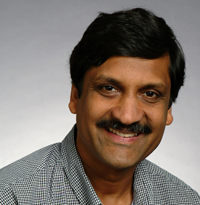
Official MIT CSAIL profile, last-update label 5 April 2022: the biography describes multicore-computing work and the circuits textbook. The independent official departmental page www.eecs.mit.edu/people/anant-agarwal/ identifies the same professor and lists computer architecture as a research area; its image link is www.eecs.mit.edu/sites/default/files/person-photos/agarwal_0.jpg . Historical profile wording is not used to assert a current external executive role.
Primary ABB guide. Technology Review, Performance Characteristics, printed pp.8–9, discusses equivalent excitation and through impedances. Burdens, printed p.13, defines secondary loading and its effect on ratio/phase errors, distinguishes standard from actual burdens, and tabulates impedance and VA at specified secondary current. No present-day accuracy standard is inferred from this historical guide.
Primary analyzer documentation. S-Parameters defines the output/input index order; Common Measurements with S-Parameters distinguishes reflection and transmission; Receiver Measurements and Ratioed Measurements describe reference/test receiver ratios.
Primary Pulse Width control page. Width is measured between rising and falling 50% crossings; duty-cycle entry provides an alternative setting. The page distinguishes period constraints from the width value.
Eamon Nash is an applications engineer whose technical writing connects amplifier models with measurements of real circuits. His A Practical Review of Common Mode and Instrumentation Amplifiers by Eamon Nash explains how finite common-mode rejection ratio converts a shared input disturbance into output error, even when the desired signal is differential.[ref]
A Practical Review of Common Mode and Instrumentation Amplifiers by Eamon Nash. Equations (1)–(2) and discussion of frequency-dependent rejection
His later RF-modeling article compares simulated and measured amplifier behavior. Small-signal scattering parameters describe linear gain and matching, but additional data are needed for noise and nonlinear compression. One demonstrated limitation is especially instructive: a model can reproduce amplitude compression while missing signal-dependent phase distortion because its input data contain only small-signal phase. That makes the disagreement scientifically useful evidence about what information the model lacks.[ref]
https://www.analog.com/en/resources/analog-dialogue/articles/nonlinear-simulation-of-rf-ic-amplifiers-in-keysight-genesys-and-systemvue.html. Author byline and AM-to-AM and AM-to-PM Distortion section

A gas discharge is electrical conduction through a gas containing mobile charged particles. An applied electric field accelerates electrons; collisions can cause ionization, generating additional electrons and ions. A sustained discharge requires charge-production and electrode-emission processes to offset losses, rather than merely the presence of a few initially charged particles.
In a uniform Townsend avalanche model, gives across a gap . If each arriving positive ion releases on average electrons from the cathode, the self-sustaining threshold is . Combining that condition with the field dependence of gives the Paschen law.[ref]
A motivating measurement fixes the gas, electrode material and gap, varies pressure and records the onset electric potential difference with a current-limited source. A pressure gauge and current measurement distinguish the breakdown threshold from the later conducting regime. At larger currents, space charge and heating can invalidate the uniform-field avalanche approximation.
Pinned article: Introduction to the OurBigBook Project
Welcome to the OurBigBook Project! Our goal is to create the perfect publishing platform for STEM subjects, and get university-level students to write the best free STEM tutorials ever.
Everyone is welcome to create an account and play with the site: ourbigbook.com/go/register. We belive that students themselves can write amazing tutorials, but teachers are welcome too. You can write about anything you want, it doesn't have to be STEM or even educational. Silly test content is very welcome and you won't be penalized in any way. Just keep it legal!
Intro to OurBigBook
. Source. We have two killer features:
- topics: topics group articles by different users with the same title, e.g. here is the topic for the "Fundamental Theorem of Calculus" ourbigbook.com/go/topic/fundamental-theorem-of-calculusArticles of different users are sorted by upvote within each article page. This feature is a bit like:
- a Wikipedia where each user can have their own version of each article
- a Q&A website like Stack Overflow, where multiple people can give their views on a given topic, and the best ones are sorted by upvote. Except you don't need to wait for someone to ask first, and any topic goes, no matter how narrow or broad
This feature makes it possible for readers to find better explanations of any topic created by other writers. And it allows writers to create an explanation in a place that readers might actually find it.
Figure 1. Screenshot of the "Derivative" topic page. View it live at: ourbigbook.com/go/topic/derivativeVideo 2. OurBigBook Web topics demo. Source. - local editing: you can store all your personal knowledge base content locally in a plaintext markup format that can be edited locally and published either:This way you can be sure that even if OurBigBook.com were to go down one day (which we have no plans to do as it is quite cheap to host!), your content will still be perfectly readable as a static site.
- to OurBigBook.com to get awesome multi-user features like topics and likes
- as HTML files to a static website, which you can host yourself for free on many external providers like GitHub Pages, and remain in full control

Figure 2. You can publish local OurBigBook lightweight markup files to either OurBigBook.com or as a static website.
Figure 3. Visual Studio Code extension installation.
Figure 5. . You can also edit articles on the Web editor without installing anything locally. Video 3. Edit locally and publish demo. Source. This shows editing OurBigBook Markup and publishing it using the Visual Studio Code extension. 
- Infinitely deep tables of contents:


All our software is open source and hosted at: github.com/ourbigbook/ourbigbook
Further documentation can be found at: docs.ourbigbook.com
Feel free to reach our to us for any help or suggestions: docs.ourbigbook.com/#contact