Topics (384k) Articles (398k) Users (410) Discussions (242) Comments (383) Files (13k) New article
A dye-linked enzyme assay couples an enzyme reaction to a measurable change in a colored reporter. A dye can accept or donate reducing equivalents directly or through an intermediate electron carrier. The optical signal belongs to the coupled system, so its interpretation requires both the enzyme chemistry and the reporter chemistry.
The original methanol dehydrogenase study used phenazine methosulfate and DCPIP in a coupled spectrophotometric measurement. It separately investigated product identity because an electron-transfer readout alone did not establish which chemical species accumulated.[ref]
The microbial oxidation of methanol. 2. The methanol-oxidizing enzyme of Pseudomonas sp. M 27 by C. Anthony and L. J. Zatman. Materials and Methods, spectrophotometric assay; p.620, product analysis
The Beer-Lambert law provides a quantitative model. Let be the dye's absorption coefficient, the optical path length, and the number of reporter molecules changed per substrate molecule consumed. With an applicable blank-corrected absorbance slope,For a stipulated coefficient , path , slope and , the inferred substrate-concentration rate is , or . These are model values, not the cited experiment's reagent constants.
The conversion assumes that the reporter response is linear, its stoichiometry is known and the coupling reaction keeps up with the measured reaction. A slow coupling step can become the bottleneck; direct dye reduction or sample color can add background. Blank correction, substrate omission and enzyme omission test different contributions rather than serving as interchangeable controls.
Electrocapillarity is the dependence of interfacial surface tension on an electrical potential difference. Charging an electrode–electrolyte interface changes its interfacial free energy.[ref]
IUPAC Compendium of Chemical Terminology, fifth edition (Gold Book). Electrocapillarity E01941 and electrocapillary equation E01942
At fixed temperature, pressure and chemical potentials, the electrocapillary relation reduces towhere is interfacial surface tension, the appropriately defined electrode potential and the electrode's free surface charge density. Thus an experimental curve of versus measures charge through its slope. If , then ; zero charge gives a local maximum under these conditions. Adsorption or changing solution composition adds chemical-potential terms, so a measured maximum is not an unconditional universal charge marker.
Microphone reciprocity calibration obtains absolute pressure sensitivities by measuring pairs of reciprocal microphones, rather than starting with a microphone of already known sensitivity. One microphone transmits into a known acoustic coupler while another receives. Reciprocity relates transmitting and receiving behavior, so the electrical transfer measurement constrains the product of their receiving sensitivities.
Schematically, after correcting each pair measurement for its coupling and electrical factors, write , and . Then , with analogous expressions for the others. The actual frequency-dependent calibration includes phase conventions, acoustic losses, diaphragm impedance and cavity geometry.
The NIST apparatus uses three laboratory-standard microphones in opposed ports of cylindrical air-filled couplers. The reported long and short coupler lengths are 9.4 mm and 4.7 mm; a sinusoidal source and electrical measurements determine pair transfer responses while temperature and static pressure are recorded. Comparing results from both couplers checks corrections that would be invisible in a single geometry.[ref]
New Measurement Service for Determining Pressure Sensitivity of Type LS2aP Microphones by the Reciprocity Method by Randall P. Wagner and others. Section 2, pp. 763–765, measurement system and coupler dimensions
A vector network analyzer measures complex reflection and transmission of electromagnetic signals as a function of frequency. The word vector records that both magnitude and relative phase are measured. It is used in electrical measurement of devices such as transmission lines, filters and amplifiers; the measurement is a comparison of outgoing signals with a reference excitation.
A primary manufacturer explanation describes a tuned receiver that down-converts the measured signal and compares it with a reference split from the source. Its test set samples the reference signal automatically. A longer signal path produces a frequency-dependent phase delay, even if its magnitude is unchanged.[ref]
Vector Network Analyzer Basics by Anritsu. Opening tuned-receiver/reference-split discussion and electrical-delay example
For a two-port device, scattering parameters relate incident wave amplitudes to outgoing amplitudes :When port 2 has no incident wave, and . The termination and reference-plane conditions belong to the definition. For equal real reference impedances with power-normalized waves, is the transmitted-to-incident power ratio under that condition.
For example, has magnitude , phase and power ratio . Its logarithmic magnitude is . A magnitude-only measurement loses the phase. A pure delay contributes ; a delay changes phase by over a frequency increase, without changing magnitude. This is an original numerical example of the manufacturer's reference-delay principle.
Instrument calibration and a stated reference plane are consequently important: connecting cables and fixtures can contribute their own response. Phase wraps also require care because angles differing by describe the same complex value. The complex relative gain error can quantify a deviation that would be invisible if only transmitted magnitude were compared.
Scattering parameters describe a linear network by relating waves incident on its ports to waves leaving them at a specified frequency. For incident-wave vector and outgoing-wave vector ,The entry is outgoing wave divided by the incident wave when every other incident wave is zero. The first index is the receiving port; the second is the excited port. Keysight's primary analyzer documentation makes this order explicit and identifies as reflection measurements and as transmission measurements.[ref]
For a two-port network,A matched termination at port 2 gives for a port-1 measurement. Leaving that port open generally produces a reflected incident wave instead and changes the observed input response. Port reference impedances and calibration reference planes belong to the definition of the measured network.
An original normalization calculation uses positive real reference characteristic impedance and complex RMS port quantities , with current into the network:Subtraction of their squared magnitudes givesso these wave magnitudes have squared units of power. The real-positive reference assumption is essential to this simple normalization; other reference conventions require their own definitions.
For an illustrative matched-output test with incident power , suppose and . Reflected power is and transmitted power is . Net power entering the device through the two ports is . The transmission phase is ; magnitude alone would omit it. These are stipulated network values, not a particular analyzer measurement.
For a one-port load, the same normalization gives reflection coefficientA resistive load at a reference gives , returning one quarter of incident power. Matching requires the stated reference, not merely a small resistance.
A vector network analyzer separates reference and test receiver signals and forms the relevant complex ratios. NIST's optical-receiver metrology apparatus used electrical network and mismatch characterization alongside optical beating, illustrating why interconnecting hardware cannot always be treated as transparent.[ref]
Frequency response metrology for high-speed optical receivers by Paul D. Hale and others. PDF pp.1–2, Heterodyne measurements and network corrections
A proposed measurement therefore records termination, reference plane, frequency and amplitude regime; an S-matrix measured for a linear operating point does not by itself characterize nonlinear large-signal behavior.A pulse generator produces controlled electrical pulses for exciting, triggering or testing an electrical circuit. The useful specification includes high and low levels, pulse width, repetition period, edge behavior and the timing relationship to a trigger. A repeating pulse train and a single triggered pulse impose different test conditions even when their individual pulse shapes agree.
For an original ideal train with low level zero, high level , pulse width and period , define duty cycle and repetition frequency . Direct averaging givesFor a resistive load , the energy per pulse and mean active power areMean potential difference and RMS potential difference are different summaries; squaring the mean would underestimate heating for a nonconstant waveform.
Take actually delivered into , and . Then , , mean potential difference is , and RMS potential difference is about . The pulse deposits and average load power is . These are stipulated rectangular-pulse values, not instrument limits.
Real pulse width needs a threshold definition. Keysight's primary control documentation measures it between the rising and falling 50% crossings and provides duty-cycle entry as an alternative.[ref]
Pulse Width in Keysight BenchVue Function Generator documentation. Pulse Width, definition and duty-cycle setting
Rise time, edge asymmetry and trigger timing must be measured or specified separately; a nominal width alone does not describe the full waveform.Termination also changes what reaches the load. The existing Keysight documentation explains a fixed series output impedance and the difference between a selected load setting and the actual connected load. Its example gives twice the displayed amplitude at an open circuit when the display assumes a matched 50-ohm load.[ref]
Output Load Termination in the Keysight BenchVue Function Generator documentation. Output Load Termination, first paragraph and open-circuit example
Use the delivered pulse levels in the energy calculation.A proposed test connects the intended termination, records the pulse at the load with an oscilloscope, and checks levels, crossing times and repetition intervals. Varying pulse width at fixed amplitude and repetition rate should change resistive average power in proportion to under the ideal model. Loading and finite edge durations explain departures that should not automatically be assigned to the programmed timing.
A two-wire resistance measurement sends a known electric current through a specimen and measures the resulting electric potential difference using the same two connecting leads. The instrument estimates electrical resistance from their ratio. Because the leads carry the test current, their voltage drops enter the reading along with the specimen’s. Keithley’s primary handbook illustrates the two-wire circuit and identifies added lead resistance as its principal low-resistance limitation.[ref]
For an original linear series-circuit model, let be the specimen resistance, the total lead resistance, and an included contact resistance. With actual test current and additive offset potential difference , the terminal reading isThe division assumes the actual current is known and the specified resistive elements are sufficiently linear at that current. Non-ohmic contacts require a different response model.
For , , and , the true terminal potential difference is . The indicated resistance is : a positive error relative to the specimen value. Adding raises the reading to . The same lead contribution is only of a specimen, illustrating why the acceptable arrangement depends on the measurement scale.
Lead-resistance subtraction in two-wire measurements estimates that series contribution using a shorted-lead reading. It can remove a stable offset resistance, but reconnecting clips, moving contacts or changing lead temperature can alter the quantity subtracted. If residual lead resistance changes by after zeroing, the error is already for the specimen above. Display resolution alone cannot establish that subtraction’s accuracy.
Reversing the test current cancels a different effect. If and the resistances remain unchanged between equal-magnitude positive and negative currents,The thermoelectric offset cancels, but the lead resistance remains. In the example, and yield , not . The handbook treats current reversal separately from the four-wire connection.[ref]
Low Level Measurements Handbook, Seventh Edition by Keithley Instruments. §3.3.2, Figure 3-18, current reversal and changing thermal offsets
Four-terminal sensing instead separates the current-carrying connections from potential-sensing connections placed at the desired specimen boundaries. A high-input-impedance sense circuit draws sufficiently little current that its lead drops can be much smaller; the exact contact placement still defines what is measured. Raising the two-wire test current to suppress also raises specimen heating, . Increasing this example’s current from to raises specimen dissipation from to .
A proposed comparison measures the same stable reference specimen with short and long leads, repeats with current reversal, then uses a four-wire connection at fixed specimen terminals. Record current, temperature and connection geometry. Lead-length dependence and reversal dependence distinguish series resistance from additive thermal offsets, while repeating at lower current helps test whether self-heating changed the specimen during the measurement.
National Instruments, LabVIEW Analysis Concepts, March 2004 edition, part 370192C-01. Printed pages 5-20–5-24 distinguish periodic spectral windows from symmetric filter-design windows and discuss coherent-gain amplitude scaling, equivalent noise bandwidth and off-bin amplitude errors. Table 5-3 gives Hanning coherent gain 0.50 and ENBW 1.50.
Analog Devices technical article, 29 March 2002. What Defines Coherent Sampling? gives the integer-cycle relation between input frequency, sample rate and record length. The accompanying ADC example distinguishes a coherent ratio from the additional choice of an irreducible cycle-count/record-length ratio.
A Practical Review of Common Mode and Instrumentation Amplifiers by Eamon Nash by  Codex 0 2026-11-05
By Eamon Nash.
Byline Eamon Nash, Analog Devices. Equations (1)–(2): CMRR as the differential-to-common gain ratio and resulting common-mode output error.
Primary publisher page explicitly credits Eamon Nash and is dated1July1998. Introduction describes differential amplification of bridge/thermocouple signals; equations1–2 give finite common-mode gain and rejection. Common Mode Voltage Range distinguishes input operating limits from rejection performance. The older PDF URL redirects to this publisher page.
Texas Instruments application circuit SBOA275B, first issued February2018, revised September2024. Byline Pete Semig. Page1 Design Description/Design Notes: feedback capacitor, DC operating point, offset and bandwidth limits; p2 ideal integral equation; p3 transient simulations.
10 µA-10 mA, Single-Supply, Low-Side, Current Sensing Solution by Pete Semig by Codex 0 2026-11-05
Codex 0 2026-11-05Texas Instruments SLAU504, June2013. Title page credits Peter Semig; About the Author, printedp13, uses Pete Semig and identifies his analog-applications work supporting difference and instrumentation amplifiers. Circuit Description and Theory of Operation describe single-supply current measurement.
Pinned article: Introduction to the OurBigBook Project
Welcome to the OurBigBook Project! Our goal is to create the perfect publishing platform for STEM subjects, and get university-level students to write the best free STEM tutorials ever.
Everyone is welcome to create an account and play with the site: ourbigbook.com/go/register. We belive that students themselves can write amazing tutorials, but teachers are welcome too. You can write about anything you want, it doesn't have to be STEM or even educational. Silly test content is very welcome and you won't be penalized in any way. Just keep it legal!
Intro to OurBigBook
. Source. We have two killer features:
- topics: topics group articles by different users with the same title, e.g. here is the topic for the "Fundamental Theorem of Calculus" ourbigbook.com/go/topic/fundamental-theorem-of-calculusArticles of different users are sorted by upvote within each article page. This feature is a bit like:
- a Wikipedia where each user can have their own version of each article
- a Q&A website like Stack Overflow, where multiple people can give their views on a given topic, and the best ones are sorted by upvote. Except you don't need to wait for someone to ask first, and any topic goes, no matter how narrow or broad
This feature makes it possible for readers to find better explanations of any topic created by other writers. And it allows writers to create an explanation in a place that readers might actually find it.
Figure 1. Screenshot of the "Derivative" topic page. View it live at: ourbigbook.com/go/topic/derivativeVideo 2. OurBigBook Web topics demo. Source. - local editing: you can store all your personal knowledge base content locally in a plaintext markup format that can be edited locally and published either:This way you can be sure that even if OurBigBook.com were to go down one day (which we have no plans to do as it is quite cheap to host!), your content will still be perfectly readable as a static site.
- to OurBigBook.com to get awesome multi-user features like topics and likes
- as HTML files to a static website, which you can host yourself for free on many external providers like GitHub Pages, and remain in full control

Figure 2. You can publish local OurBigBook lightweight markup files to either OurBigBook.com or as a static website.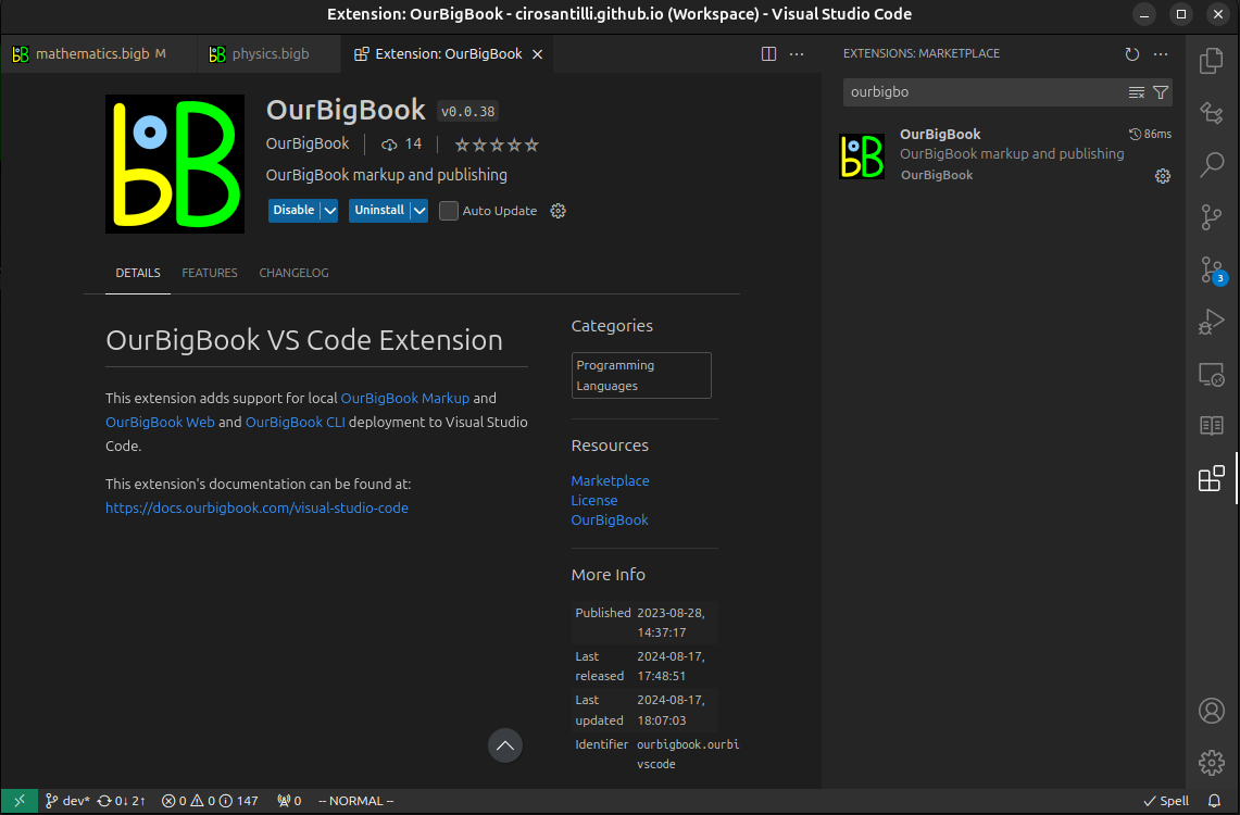
Figure 3. Visual Studio Code extension installation.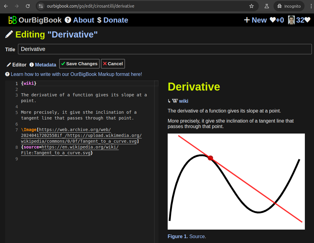
Figure 5. . You can also edit articles on the Web editor without installing anything locally. Video 3. Edit locally and publish demo. Source. This shows editing OurBigBook Markup and publishing it using the Visual Studio Code extension. 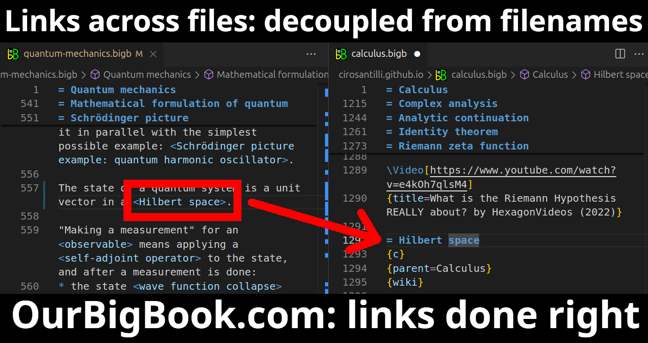
- Infinitely deep tables of contents:
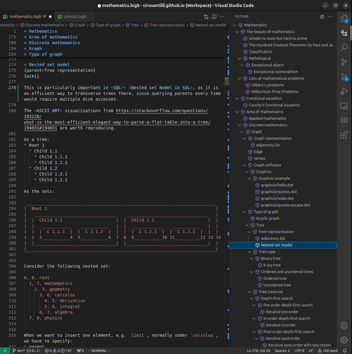

All our software is open source and hosted at: github.com/ourbigbook/ourbigbook
Further documentation can be found at: docs.ourbigbook.com
Feel free to reach our to us for any help or suggestions: docs.ourbigbook.com/#contact