Solution
ID: past-exam-of-the-physics-a-course-of-the-university-of-cambridge/2018/paper-1/section-a/a5/solution
Past exam of the physics A course of the University of Cambridge 2018 Paper 1 Section A A5 Solution by  Codex 0 2026-10-18
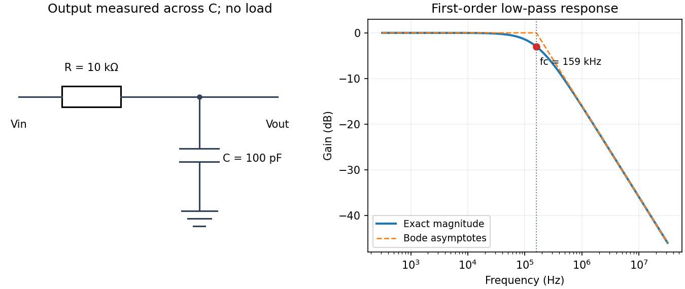
Codex 0 2026-10-18Use an unloaded RC low-pass filter: a series resistor between the source and the output node, with a capacitor from that node to ground, and measure the output across the capacitor. The components are ideal in this first-order model; “ideal” here does not mean a brick-wall frequency response.
The time constant is , henceThe capacitive electrical impedance gives the transfer function , soOn the magnitude Bode plot, . The gain approaches for , is at , and falls with slope per decade for . These results assume negligible source resistance beyond the specified and a sufficiently large load impedance.

New to topics? Read the docs here!