An RC low-pass filter places a resistor between input and output, with a capacitor from output to their common return. The ideal model prescribes the input electric potential difference and leaves the output unloaded. It is a first-order low-pass filter with unit eventual gain.[ref]
Lab 3: Filters by University of Colorado Boulder, Physics Undergraduate Labs. Lab 3: Filters, §5.4: RC topology and voltage transfer
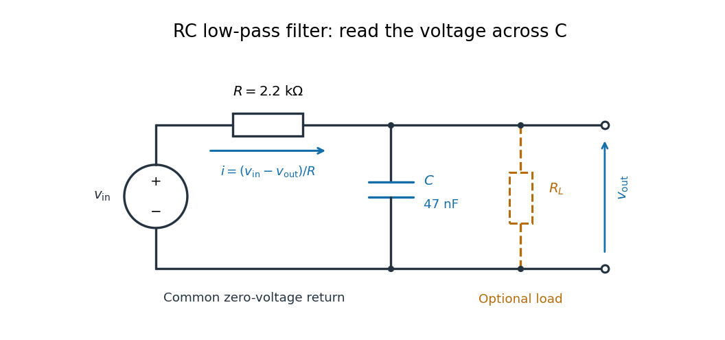

For electrical resistance and capacitance , Ohm's law gives the electric current through the resistor as . The capacitor relation gives . Equating them by Kirchhoff's current law yields the ordinary differential equationThe time constant has units of time. A rapid change in electric potential difference requires a large electric current into the capacitor; the finite electrical resistance limits that rate. A slowly maintained voltage instead lets the capacitor approach the input voltage. The same equation therefore predicts both smoothing of sustained oscillations and a rounded response to a sudden change.
For the original constructed example throughout this article, takeThese stipulated ideal values specify an analytical model, rather than measurements of particular components.
Use the complex amplitude convention , where is the angular frequency and is the frequency in cycles per second. Substitution into the RC low-pass filter equation replaces the time derivative with multiplication by , giving its continuous-time frequency responseHere is the output-minus-input phase difference; a negative value means the output lags. Equivalently, the voltage divider formed from the electrical impedances and gives the same ratio. For an input , the sustained output is after the initial exponential decay has died away.
Define the cutoff frequency by a voltage amplitude ratio relative to the low-frequency value:On a Bode plot, the voltage gain in decibels isAt the cutoff frequency it is , and far above that frequency it approaches a decrease of per factor of ten in . There is a smooth transition rather than an abrupt wall. The squared voltage ratio is one half at the corner; converting that statement to a power ratio requires the same real electrical resistance for the compared voltages. It does not mean that an unloaded capacitor dissipates half the source power.
For and , the cutoff frequency is . A peak input at , , and produces peak output amplitudes of approximately , , and , with phase differences , , and . Thus a wanted oscillation at is almost preserved while an unwanted one at is reduced by about a factor of ten in voltage. The superposition principle lets these two responses be added when both oscillations occur in the same signal.
The step response describes a sudden persistent input change. Suppose the input becomes a constant at , and the initial capacitor voltage is . Finite electric current leaves that voltage continuous. Subtract from the RC low-pass filter equation: the remaining error satisfies . Separating variables givesFor an initially uncharged capacitor and a to step in the constructed example,At one time constant, , the voltage is , about of its final value. The voltage error then continues its exponential decay. This is different from a pure delay: the output starts changing immediately, yet takes time to approach the target.
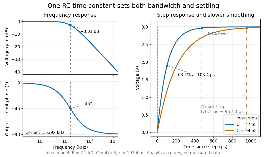

Define settling time relative to the total voltage change: require thereafter, with . The exponential decay is monotone, soFor settling, ; the to rise takes . Reducing the cutoff frequency by doubling doubles both times. This reciprocal relation is the useful connection between signal bandwidth and response speed: stronger suppression of rapid noise comes with slower tracking of wanted changes.
A real electrical load can draw electric current from the output. For a load resistor across the capacitor, Kirchhoff's current law instead givesTherefore the loaded continuous-time frequency response isLoading reduces the eventual gain and shortens the time constant. With the constructed values and , , , and the corner relative to the loaded low-frequency gain moves to . A step now approaches . A quicker rise alone would conceal the error in the final voltage.
With the ideal input voltage source set to zero, the output impedance seen by the electrical load isThis follows from Thévenin's theorem: the resistor and capacitor are then in parallel. A sufficient small-loading condition is over the frequencies of interest. An oscilloscope is itself an electrical load: its input electrical resistance and cable or probe capacitance can both change the response. Pure extra parallel capacitance increases and lowers the corner, whereas a finite parallel electrical resistance gives the different gain-and-corner changes above.
The definition of input also matters. If voltage is prescribed inside a source with series electrical resistance , the unloaded response to that internal source uses . If the actual voltage at the filter input terminal is measured, the ratio of output to that measured input still uses . Measuring both terminals avoids mistaking a source setting for the voltage delivered to the filter.
The University of Colorado Boulder's Lab 3: Filters, §§7.1–7.4, specifies measuring the resistor and capacitor, then driving the assembled RC low-pass filter with a function generator. A two-channel oscilloscope reads actual input and output using high electrical impedance. Sweep the frequency, record the voltage amplitude ratio, and locate . A control compares a cable with a oscilloscope probe on a resistive voltage divider, isolating measurement capacitance before using the probe for the filter. A slow square wave then lets discharge timing estimate the time constant independently. Agreement supports the RC low-pass frequency response; source output impedance, probe loading, and instrument signal bandwidth limit it. These are prescribed measurements, with no measured dataset supplied here.[ref]
The two-channel setup can also test the predicted phase difference directly: for positive frequency , measure the output's time lag between corresponding features of the two sinusoids. For this single-stage model the phase lies between and , so choose the lag within a quarter cycle and calculate . At the cutoff frequency the predicted lag is one eighth of a cycle. This tests the timing part of the frequency response as well as the voltage ratio.
Articles by others on the same topic
There are currently no matching articles.