Phase folding of a light curve
ID: phase-folding-of-a-light-curve

Phase folding of a light curve maps timestamps onto a trial cycle of duration . Given a reference time , define the phase in cycles bywhere is the fractional part, using the floor function also for negative . Plot brightness against rather than ; measurements separated by an integer multiple of occupy the same phase. For a periodic function , this reveals the shared shape of many cycles. Folding changes coordinates; it neither averages samples nor chooses the correct by itself. Welsh et al.'s folded Kepler plot separates the exoplanet transit and orbital brightness modulation. [ref]
https://www.ucolick.org/~jfortney/papers/Welsh10.pdf. Welsh et al. (2010), figure 1
.The second figure uses a completely synthetic trapezoidal dip: days, day, and the same depth and four-hour duration as the first figure. Different colours identify four successive cycles. Correct folding superimposes the dips; a wrong trial orbital period spreads them out. If , the centre of the th repeated event shifts by approximately cycles when folded on , for . With days, the fourth plotted event is displaced by cycles. Transit-timing variations can also smear a constant-period fold, so retain the original timestamps and inspect individual events.
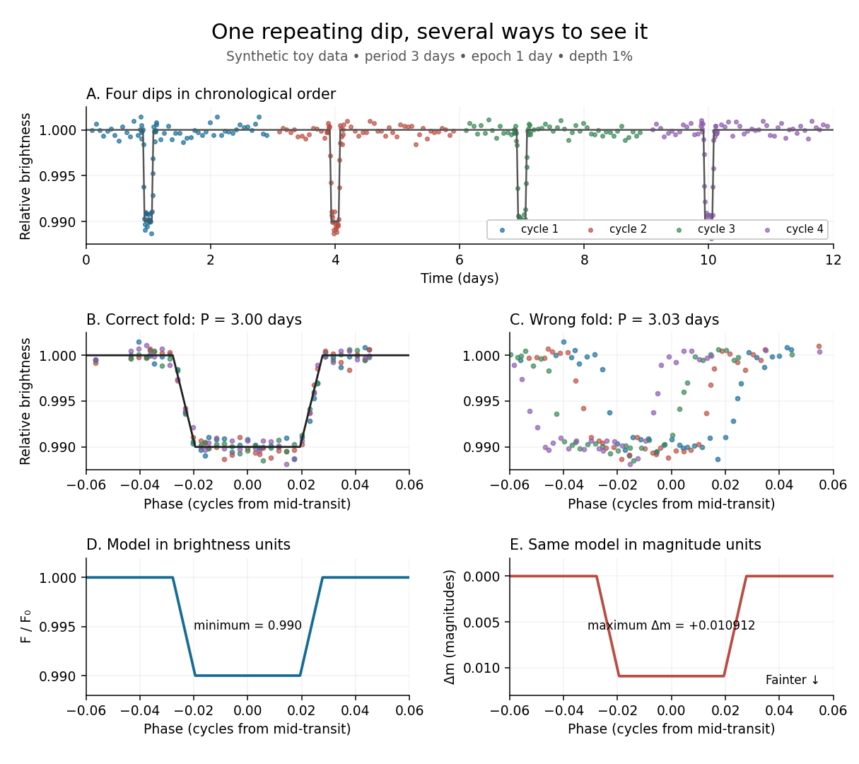
Toy phase folding: repeated synthetic dips align at the correct period; a flux dip becomes a positive magnitude change
. Details. 
One may combine nearby phases with a weighted mean, but the uncertainty reduction requires assumptions. For independent measurements with common standard deviation and effectively the same expected brightness within the bin, their arithmetic mean has standard deviation . Thus sixteen independent -precision samples give precision on that phase-bin mean. Shared calibration errors, changing starspots, and bins wide enough to mix ingress with out-of-transit brightness violate these assumptions. A folded plot can conceal changes between cycles. Gaussian process models can represent correlated variability and interpolate irregular samples, but their predictions and uncertainties depend on their assumed covariance function.
The bottom panels show the same model as relative brightness and as magnitude difference in one fixed photometric passband with a fixed magnitude zero point:A dip to gives magnitudes: fainter means a larger apparent magnitude. The figure places larger magnitude differences lower on the page so the two dip shapes are easy to compare; reversing that plotting convention does not change the formula. For and small , expansion of the logarithm gives . The exact transform is nonlinear: transforming an exposure's mean brightness is generally different from averaging its instantaneous apparent magnitudes. The ordinary logarithm cannot be applied to a nonpositive background-subtracted measurement; keep such measurements and their uncertainties in brightness units for an appropriate statistical model.
New to topics? Read the docs here!