This is an example of how paging operates on a simplified version of a x86 architecture to implement a virtual memory space with a
20 | 12 address split (4 KiB page size).This is how the memory could look like in a single level paging scheme:
Links   Data                    Physical address

      +-----------------------+ 2^32 - 1
      |                       |
      .                       .
      |                       |
      +-----------------------+ page0 + 4k
      | data of page 0        |
+---->+-----------------------+ page0
|     |                       |
|     .                       .
|     |                       |
|     +-----------------------+ pageN + 4k
|     | data of page N        |
|  +->+-----------------------+ pageN
|  |  |                       |
|  |  .                       .
|  |  |                       |
|  |  +-----------------------+ CR3 + 2^20 * 4
|  +--| entry[2^20-1] = pageN |
|     +-----------------------+ CR3 + 2^20 - 1 * 4
|     |                       |
|     .    many entires       .
|     |                       |
|     +-----------------------+ CR3 + 2 * 4
|  +--| entry[1] = page1      |
|  |  +-----------------------+ CR3 + 1 * 4
+-----| entry[0] = page0      |
   |  +-----------------------+ <--- CR3
   |  |                       |
   |  .                       .
   |  |                       |
   |  +-----------------------+ page1 + 4k
   |  | data of page 1        |
   +->+-----------------------+ page1
      |                       |
      .                       .
      |                       |
      +-----------------------+  0
Notice that:
- the CR3 register points to the first entry of the page table
- the page table is just a large array with 2^20 page table entries
- each entry is 4 bytes big, so the array takes up 4 MiB
- each page table contains the physical address a page
- each page is a 4 KiB aligned 4 KiB chunk of memory that user processes may use
- we have 2^20 table entries. Since each page is 4 KiB == 2^12, this covers the whole 4 GiB (2^32) of 32-bit memory
Suppose that the OS has setup the following page tables for process 1:and for process 2:
entry index   entry address       page address   present
-----------   ------------------  ------------   -------
0             CR3_1 + 0      * 4  0x00001        1
1             CR3_1 + 1      * 4  0x00000        1
2             CR3_1 + 2      * 4  0x00003        1
3             CR3_1 + 3      * 4                 0
...
2^20-1 CR3_1 + 2^20-1 * 4 0x00005 1entry index entry address page address present
----------- ----------------- ------------ -------
0 CR3_2 + 0 * 4 0x0000A 1
1 CR3_2 + 1 * 4 0x12345 1
2 CR3_2 + 2 * 4 0
3 CR3_2 + 3 * 4 0x00003 1
...
2^20-1 CR3_2 + 2^20-1 * 4 0xFFFFF 1When process 1 tries to access a linear address, this is the physical addresses that will be actually accessed:
linear     physical
---------  ---------
00000 001  00001 001
00000 002  00001 002
00000 003  00001 003
00000 FFF  00001 FFF
00001 000  00000 000
00001 001  00000 001
00001 FFF  00000 FFF
00002 000  00003 000
FFFFF 000  00005 000
To switch to process 2, the OS simply sets
cr3 to CR3_2, and now the following translations would happen:linear physical
--------- ---------
00000 002 0000A 002
00000 003 0000A 003
00000 FFF 0000A FFF
00001 000 12345 000
00001 001 12345 001
00001 FFF 12345 FFF
00004 000 00003 000
FFFFF 000 FFFFF 000Step-by-step translation for process 1 of logical address
0x00000001 to physical address 0x00001001:- split the linear address into two parts:
| page (20 bits) | offset (12 bits) | - look into Page table 1 because
cr3points to it. - The hardware knows that this entry is located at RAM address
CR3 + 0x00000 * 4 = CR3:
*0x00000because the page part of the logical address is0x00000
*4because that is the fixed size in bytes of every page table entry - since it is present, the access is valid
- by the page table, the location of page number
0x00000is at0x00001 * 4K = 0x00001000. - to find the final physical address we just need to add the offset:
00001 000 + 00000 001 --------- 00001 001because00001is the physical address of the page looked up on the table and001is the offset.The offset is always simply added the physical address of the page. - the hardware then gets the memory at that physical location and puts it in a register.
Another example: for logical address
0x00001001:- the page part is
00001, and the offset part is001 - the hardware knows that its page table entry is located at RAM address:
CR3 + 1 * 4(1because of the page part), and that is where it will look for it - it finds the page address
0x00000there - so the final address is
0x00000 * 4k + 0x001 = 0x00000001
The same linear address can translate to different physical addresses for different processes, depending only on the value inside
cr3.Both linear addresses
00002 000 from process 1 and 00004 000 from process 2 point to the same physical address 00003 000. This is completely allowed by the hardware, and it is up to the operating system to handle such cases.This often in normal operation because of Copy-on-write (COW), which be explained elsewhere.
Such mappings are sometime called "aliases".
FFFFF 000 points to its own physical address FFFFF 000. This kind of translation is called an "identity mapping", and can be very convenient for OS-level debugging.When an exception happens, the CPU jumps to an address that the OS had previously registered as the fault handler. This is usually done at boot time by the OS.
This could happen for example due to a programming error:but there are cases where it is not a bug, for example in Linux when:
int *is = malloc(1);
is[2] = 1;- the program wants to increase its stack.
- the page was swapped to disk.The OS will need to do some work behind the processes back to get the page back into RAM.
In any case, the OS needs to know which address generated the Page Fault to be able to deal with the problem. This is why the nice IA32 developers set the value of
cr2 to that address whenever a Page Fault occurs. The exception handler can then just look into cr2 to get the address.The exact format of table entries is fixed by the hardware.
The page table is then an array of
struct.On this simplified example, the page table entries contain only two fields:so in this example the hardware designers could have chosen the size of the page table to b
bits   function
-----  -----------------------------------------
20     physical address of the start of the page
1 present flag21 instead of 32 as we've used so far.All real page table entries have other fields, notably fields to set pages to read-only for Copy-on-write. This will be explained elsewhere.
It would be impractical to align things at 21 bits since memory is addressable by bytes and not bits. Therefore, even in only 21 bits are needed in this case, hardware designers would probably choose 32 to make access faster, and just reserve bits the remaining bits for later usage. The actual value on x86 is 32 bits.
Here is a screenshot from the Intel manual image "Formats of CR3 and Paging-Structure Entries with 32-Bit Paging" showing the structure of a page table in all its glory: Figure 1. "x86 page entry format".
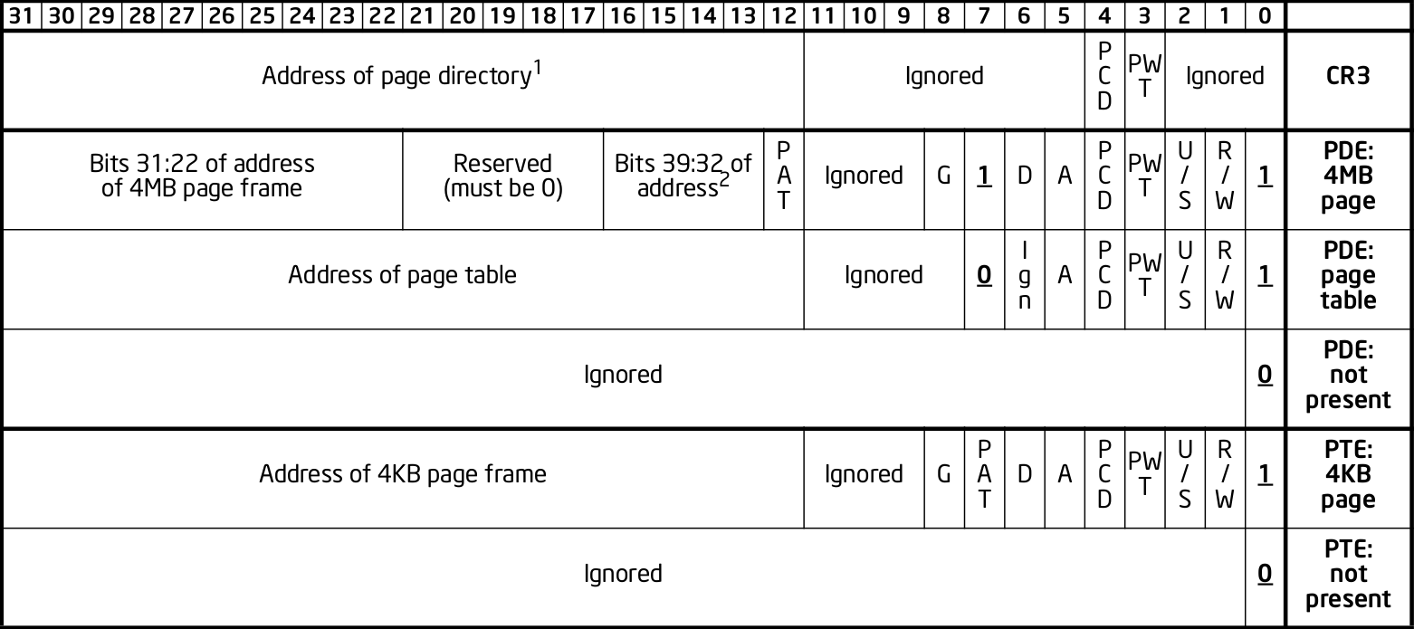
The fields are explained in the manual just after.
Why are pages 4 KiB anyways?
There is a trade-off between memory wasted in:
- page tables
- extra padding memory within pages
This can be seen with the extreme cases:
Articles by others on the same topic
There are currently no matching articles.