Heinrich Barkhausen's 1919 report used iron, a 300-turn pickup coil, moving magnet, amplified telephone readout and galvanometer. Removing iron corrected drive pickup. [ref]
The Barkhausen effect by Gianfranco Durin and Stefano Zapperi. Appendix A, p. 46: later translation of the 1919 apparatus and blank control
A modern primary experiment by Gianfranco Durin and Stefano Zapperi used annealed iron–silicon strips and amorphous alloys. A 60 cm solenoid swept a triangular magnetic field intensity; a 50-turn pickup coil, wound within 1 mm, sensed the specimen. A preamplifier with a 3–20 kHz low-pass filter preceded sampling. Measurements selected the central hysteresis region dominated by magnetic domain wall motion. Above-background threshold crossings defined event durations; integrating between crossings defined event sizes. These are reported procedures, rather than data generated for the diagrams.[ref]
Scaling exponents for Barkhausen avalanches in polycrystals and amorphous ferromagnets by Gianfranco Durin and Stefano Zapperi. pp. 1–2: apparatus, specimens and threshold integration
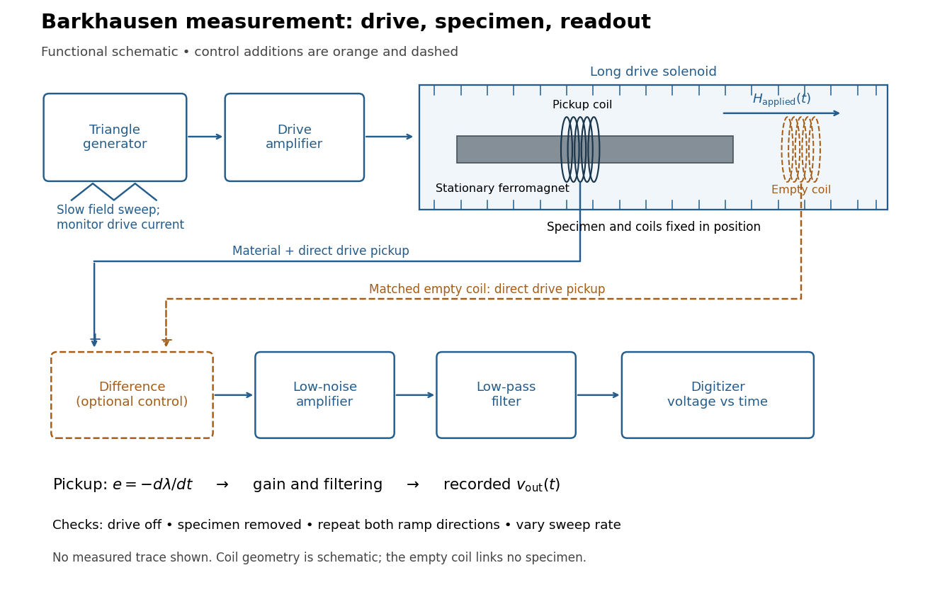
Barkhausen effect: swept magnetic field, stationary specimen and inductive readout
. Original functional schematic of the modern measurement principle. The specimen and pickup coil remain stationary; no torsional suspension or mechanical rotation is needed. The empty matching coil, difference stage and drive monitor show proposed controls, not an assertion that every component was present in the cited 2000 apparatus. The triangle indicates a drive waveform, not measured Barkhausen noise. Details.
For this stationary implementation, secure a thin ferromagnet and its pickup coil inside a longer drive solenoid, keeping their relative positions fixed. Drive the solenoid with a slow triangular electric current, monitor that electric current, and record the amplified, filtered induced electromotive force with a digitizer. A speaker may make suitable frequencies audible, but the voltage record is needed for quantitative analysis. Slow variation of the drive does not require smooth magnetization. A triangular drive supplies an approximately constant applied-field sweep rate along each ramp; it does not guarantee constant instantaneous .
A proposed control sequence makes the inference testable. First record the electronics background with no drive. Repeat the same sweep with the specimen removed, retaining coil geometry: mutual induction from the drive can itself induce a voltage. A matching empty pickup coil wired in opposition can suppress common drive pickup, after checking its matching. Compensation of air flux by an opposed coil is an established method.[ref]
The Barkhausen effect by Gianfranco Durin and Stefano Zapperi. §II.A.1, p. 4: opposed-coil compensation
Then restore the specimen, repeat both sweep directions, reduce sweep rate, and compare the same hysteresis region with fixed amplifier gain, filter and threshold. Monitor drive irregularities and mechanical vibration; either can generate spurious pulses. These controls are recommendations for the schematic, rather than undocumented controls attributed to the modern paper.A genuine material contribution should differ from the blank-coil record and change reproducibly with the magnetic preparation and sweep region. Quieting the drive tests drive-correlated pickup, but a held field need not eliminate all delayed material motion. Reversing the sweep is a consistency check on signed changes, not a demand that individual events retrace. A changing pulse count under a different filter or threshold cannot by itself establish changed microscopic dynamics. The useful inference is intermittent collective magnetization change within the instrument's signal bandwidth, with spatial detail left unresolved.
Articles by others on the same topic
There are currently no matching articles.