In the Laue method, a fixed single crystal structure receives a collimated beam containing many wavelengths. Each reciprocal lattice vector can select its own wavelength; waves with different wavelengths need not interfere with one another. For , the elastic scattering constraint gives the particularly useful testA candidate reflection requires within the source spectrum and an outgoing ray that reaches the detector. Varying wavelength changes the radius and center of the Ewald sphere while leaving the reciprocal lattice fixed. A monochromatic wave instead fixes the radius: rotating the crystal structure or varying the incident wavelength in a scan finds reflections sequentially. A white-beam photograph integrates many spectral selections in one exposure; it is not an angular scan at one known wavelength.
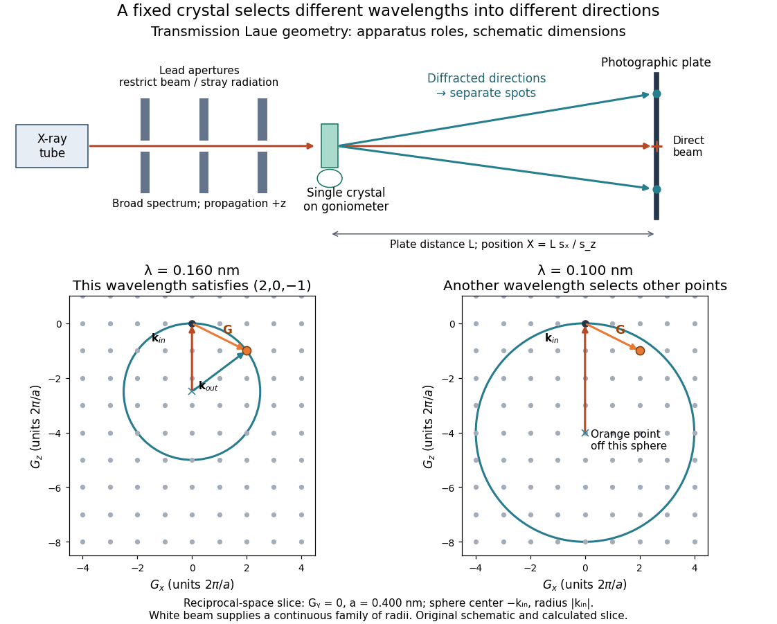

The Laue method is useful for orienting a single crystal structure: tilting it changes which reciprocal lattice vectors meet the spectral and detector conditions. Absolute scale has an ambiguity if the wavelengths are unknown. Scaling all direct lattice translations by and all selected wavelengths by leaves every outgoing direction unchanged. Independently known spectral information or length calibration is needed to remove this ambiguity.
Choose a primitive cubic lattice with , one identical point scatterer per primitive unit cell, incident direction , and the continuous wavelength band . This is a hypothetical model, not the zinc blende specimen of the Laue X-ray diffraction experiment of 1912. Write a candidate reciprocal lattice vector as with , and set . The Laue equations and elastic scattering giveA transmission photographic plate at intercepts only . Its coordinates relative to the direct beam areFor and , , and , so . Its length is one, and each component difference satisfies the corresponding Laue equations. This verifies a direction and a selected wavelength, without predicting an exposure or measured wave intensity.
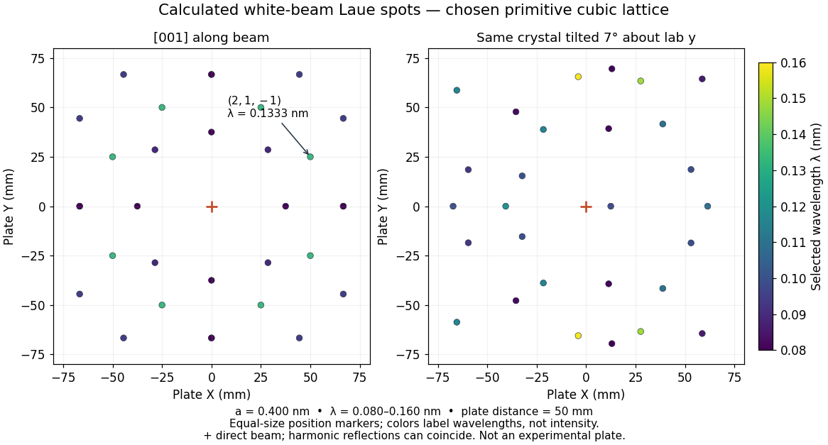
Calculated white-beam Laue method spots and their response to crystal tilt
. Original calculation for the stated primitive cubic lattice and a square detector with . Left: the cubic direction is along the incident beam. Right: rotate the same crystal structure by about the laboratory axis, keeping source and detector fixed. Color gives the selected wavelength; equal marker sizes convey positions rather than wave intensities. Harmonic reflections can overlap. Neither panel copies, simulates the chemistry of, or fits an experimental plate. Source. Details.
The first panel has fourfold symmetry because its chosen Bravais lattice, beam axis and square detector share that symmetry. For the tilted panel, apply a rotation matrix to each index vector, set , and use and . All indices with suffice: elastic scattering bounds . Thus the plotted spectral and angular selection is complete within this ideal point model and detector window. Multiples of an index vector select inversely scaled wavelengths and can land on the same spot; a white-beam spot need not identify a unique diffraction order.
Articles by others on the same topic
There are currently no matching articles.