Follow the binary decision diagram from its top decision node to a terminal node, choosing the outgoing arrow specified by each tested Boolean variable. If , the left decision node returns , independently of . If , the right decision node returns one when and otherwise returns . Thus the truth table, with rows in the order , is:
Thus the output column of the truth table, in the displayed order, is . In particular, the skipped test on the left does not constrain : both values give the same result.
Splitting the Boolean function according to the first tested Boolean variable givesThe identity follows by considering and . Using it and distributing Boolean conjunction over Boolean disjunction,The first two terms combine to because . This also explains the truth table: always makes the output one, while with the output is one exactly when both and are one.
For a complete binary decision tree with variable ordering of a binary decision diagram , first test , then , then on every branch. The four Boolean cofactors after the first two tests are
The eight terminal nodes, read from left to right in the figure, are . The repeated tests are intentional: this is the full binary decision tree before any reduction.
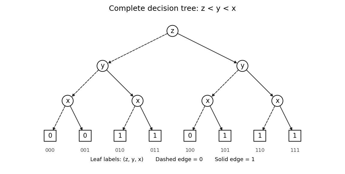
For example, the branch ends at one, whereas ends at zero. This checks the dependence on that must survive the later reduction.
A reduced ordered binary decision diagram is obtained by sharing equal terminal nodes, removing a decision node whose two children are equal, and sharing decision nodes with the same tested Boolean variable and the same ordered pair of children. Apply these rules to the binary decision tree in part (c) as follows.
- Merge the three zero terminal nodes into one zero terminal node, and merge the five one terminal nodes into one one terminal node.
- At the decision node has children . Remove it and redirect its incoming arrow to zero.
- At and the two decision nodes each have children . Remove both and redirect their incoming arrows to one.
- The remaining decision node, at , has children , so retain it.
- The decision node under now has children , while the one under has children . These are different, so neither can be merged or removed. The top decision node also has different children.
The left panel below is therefore the resulting reduced ordered binary decision diagram. Its full description is
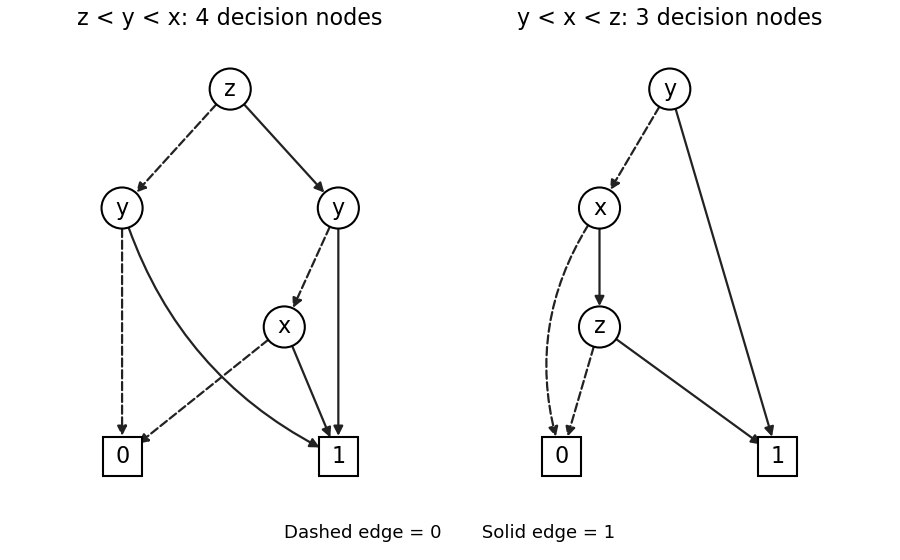
Reduced ordered decision diagrams: reversing the given order preserves its size, while testing y first saves one decision node
. Details. The original binary decision diagram also has four decision nodes and two terminal nodes, and is already reduced for : the two decision nodes have different children and no decision node has two equal children. Thus reversing the order has not made this example smaller. Indeed is unchanged by interchanging and , and the new binary decision diagram is the original one with those two labels exchanged. The uniqueness of a reduced ordered binary decision diagram applies to a fixed variable ordering of a binary decision diagram; it does not assert that every ordering has the same size.
Choose the variable ordering of a binary decision diagram . The Boolean cofactor with is the constant one, while the Boolean cofactor with is . Consequently the right panel in part (d) has the following arrows:Here an entry such as denotes the zero arrow to the decision node. There are vertices: three decision nodes and two terminal nodes, saving one decision node relative to either of the previous orderings. Testing first is effective because its one branch settles the entire Boolean function immediately. The ordering works equally well.
This is also minimal among ordinary binary decision diagrams for this Boolean function. Each Boolean variable is essential: setting leaves ; setting leaves ; and setting leaves . If a Boolean variable were never tested, the represented Boolean function could not depend on it. Thus at least three decision nodes are necessary, and the construction attains that bound.
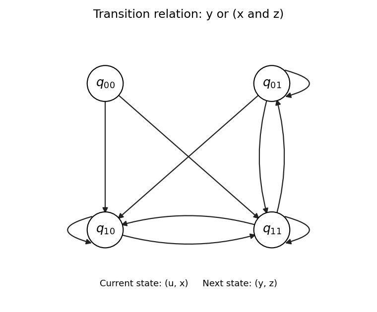
A transition relation requires an explicit interpretation of the Boolean variables as current and next state bits. Take the four states . Encode the current state by and the next state by , and defineThe extra current bit is deliberately unused by the Boolean formula. A four-state transition system normally needs four bits to describe a pair of states; a Boolean formula using only three of them simply describes a transition relation independent of the fourth bit.
When , the condition is , so the permitted next states are and . When , the condition is , so the permitted next states are . The resulting adjacency matrix, with rows and columns both ordered , isThe directed graph below plots all ten directed edges, including the three self-loops. No arrow enters , but it is a valid state with two outgoing arrows. Every state has a successor. As permitted, no initial states are distinguished.


Articles by others on the same topic
There are currently no matching articles.