Use the explicit printed width law . Its wetted area and hydrostatic pressure integral areAssuming hydrostatic pressure, a horizontal prismatic bed and cross-sectionally uniform velocity, volume conservation and momentum conservation give the prismatic-channel shallow water equationsEquivalently,The coefficient matrix in variables is . Its eigenvalues and the corresponding gravity-wave speed areFor these eigenvalues are distinct and real, establishing strict hyperbolicity in the hyperbolic partial differential equation sense. Since , substitution in the two equations showsFor example . This provides both the slopes and the conserved characteristic quantities. At a dry bed , strict hyperbolicity degenerates and the front is interpreted as the limit from positive depth.
The descriptive word “parabolic” alone would normally suggest and different coefficients. The explicit width in the PDF determines the calculation here; it must not be silently replaced by that other geometry.
Put the broken dam at and let . A dry bed is assumed downstream. The left-family rarefaction wave joins the undisturbed reservoir to the dry front. The other Riemann invariant is fixed at . Within the fan its characteristic speed equals , soThus the dry-bed dam break with cubic wetted area has the fieldsVelocity is not a meaningful fluid quantity in the dry region; its wet-side limiting value is . The upstream head travels at , while the front travels at the stated constant speed in this inviscid model.
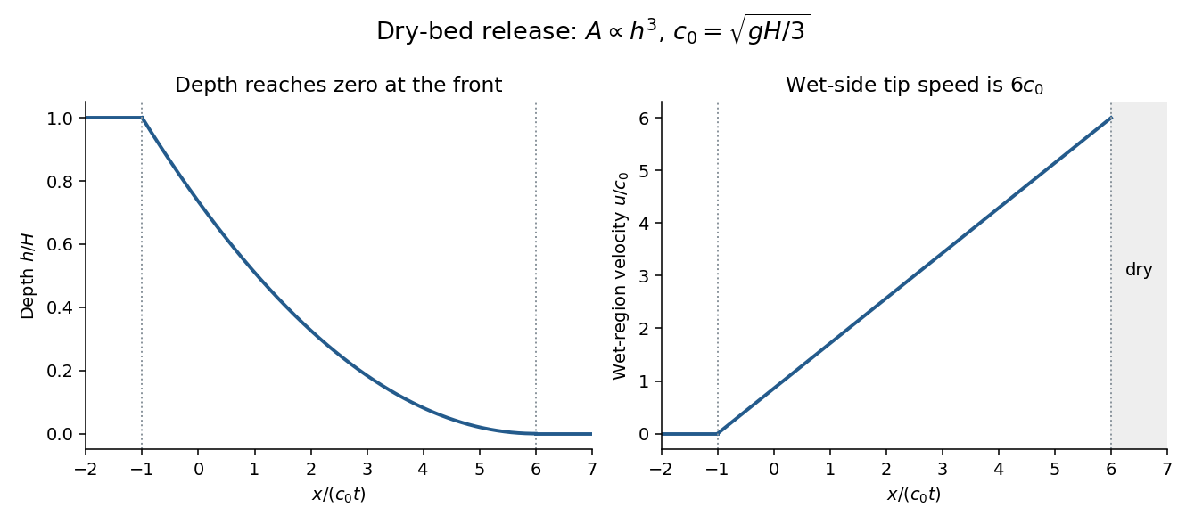
Bottom drag slows the flow and changes the dry-tip structure, where the depth is small and bed stress per unit fluid mass becomes especially important. It can replace the inviscid zero-depth high-speed tail by a drag-controlled nose. An exact altered profile or front speed requires a specified drag law; the inviscid speed should not be extrapolated to a thin real irrigation-channel front without that qualification.
Treat the newly placed sand barrier as impermeable during the initial release. The downstream isolated reservoir occupies with depth and has finite volume . The remaining upstream water stays behind the barrier; it does not continuously feed the released region. Assume so that the shallow-water approximation is appropriate.
Until the rarefaction head reaches the barrier atthe previous dam-break solution is unchanged on the released side. The wall imposes . After , a reflected downstream family adjusts the flow near the wall. It is a lowering/depletion adjustment, not a new upstream supply. The upstream depth decreases, the finite water volume spreads downstream, and the unmodified simple-wave region shrinks relatively.
The leading characteristic of this adjustment can be determined exactly without solving the whole reflected region. In the still-unmodified fan,Integrating gives the finite-reservoir reflection of a cubic-area dam-break rarefaction:The solution to the right of this curve is still the original fan. Crucially at every finite time. Therefore the ideal inviscid dry tip remains at : finite reservoir volume does not by itself justify an immediate change to that front law. Only a vanishingly small amount of fluid occupies its very thin forward tail at late times. Bottom drag, leakage or other front physics changes this conclusion.
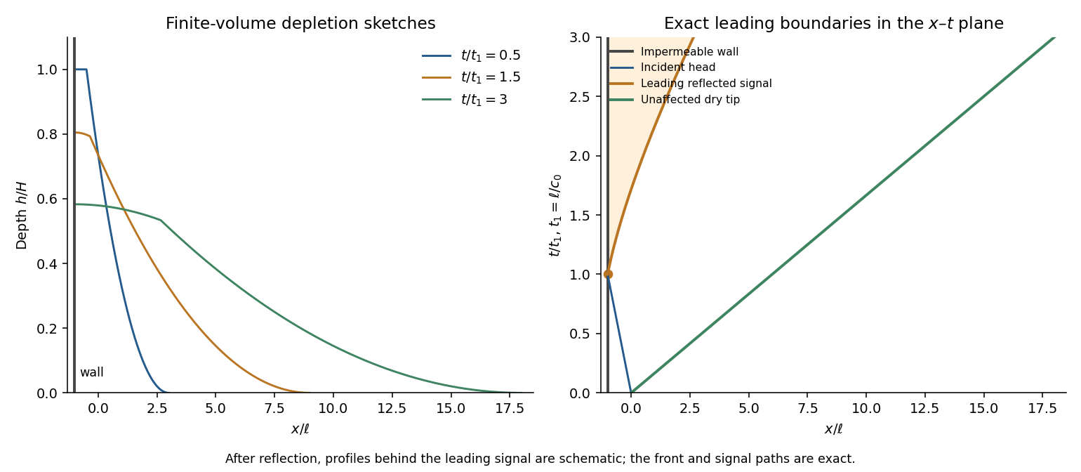


The profiles behind the reflected edge are schematic; there the two characteristic families interact and the original one-invariant fan no longer supplies the complete fields. The x–t diagram distinguishes the wall, the incident head, the exact reflected leading edge and the unaffected dry-tip trajectory.
Assume quasi-steady saturated Darcy flow, hydrostatic pore pressure, a long shallow barrier, isotropic intrinsic permeability of a porous medium , an impermeable lined base, and negligible capillarity. Maintain upstream and downstream free-surface heads at and . The Dupuit approximation neglects vertical velocity except in small entrance/exit regions. Let be the fluid's dynamic viscosity and its hydraulic conductivity.
Since the pressure is , the superficial Darcy velocity is , uniform with depth at fixed . Integrating over the printed channel width givesThe steady discharge is constant, so integration with the two head boundary values gives Dupuit flow in a channel with cubic wetted area:Here is total volume per time, including the changing channel width. The pore-space mean speed is . Thus porosity affects storage and pore transit time but does not separately multiply this steady discharge when is the intrinsic permeability in Darcy's law. If “permeability” is instead supplied as hydraulic conductivity, use that value directly for . An exact seepage-face/free-boundary calculation near the outlet would go beyond the shallow Dupuit model.
Because , the lower layer is saturated along the entire barrier. Both layers have the same horizontal head gradient but different Darcy velocities. Integrating their conductivity over the actual cross-section gives the transmissivityThe total discharge is . Hence , givingThis is a parallel-layer conductivity integral, not a series-resistance average: the layers share the horizontal pressure drop. It reduces to the previous result when . The assumption is important; if the downstream free surface cuts the lower layer, the transmissivity and its head integration must be split into different saturation regimes.
Articles by others on the same topic
There are currently no matching articles.