Use five resource qubits, all initially , and prepare the graph state with edges , , , . The labels here identify resource vertices; logical wire 1 travels from vertex 1 to 3, and logical wire 2 travels from 2 to 4 to 5. Each edge is a Controlled-Z gate, and these entangling gates commute, so all can be applied when preparing the resource.
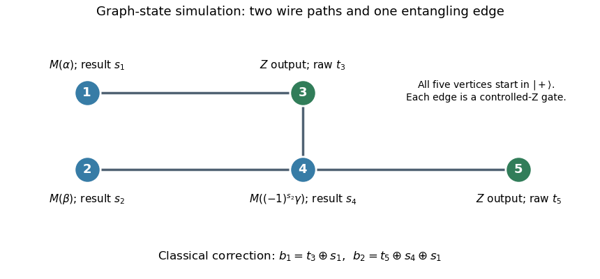
Five-vertex graph resource, adaptive measurement angle, and classical output corrections for the two-qubit circuit
. Details. 
Measure vertex 1 in the equatorial qubit measurement basis at angle , with outcome , and vertex 2 at angle , with outcome . These measurements can be simultaneous. The one-bit teleportation lemma leaves the state on vertices 3 and 4, before the last teleportation, equal up to global phase toIndeed commuting the two initial byproducts through creates precisely the crossed factors. The unused edge from 4 to the fresh vertex 5 is the last one-bit teleportation link.
Measure vertex 4 at angle , with outcome . By the printed J gate propagation identities,Thus the remaining two-qubit quantum state isup to global phase, where is the desired circuit output relabelled onto vertices 3 and 5. The sign choice cancels the unwanted angle reversal caused by the frame on vertex 4.
Finally measure vertices 3 and 5 in the computational basis, obtaining raw results . The Pauli Z gate affects only phases, while the Pauli X gate flips a computational result. The five-vertex graph-state circuit simulation therefore outputsThis deterministic classical correction reproduces the ideal joint probability distribution for every preceding measurement branch. The final fixed-basis measurements may share the second layer with the adaptive measurement of vertex 4, because their projectors act on different vertices; measuring them afterwards is also valid.
Replace every CNOT gate by . The resulting quantum circuit contains only Hadamard gates and Controlled-Z gates. Realize each Hadamard gate by a fresh one-bit teleportation link measured at angle zero, so every internal measurement is in the fixed basis. Insert a graph edge between the current wire vertices for each Controlled-Z gate. This gives a suitable graph state because the inputs are , and entangling gates can be moved to resource preparation: they commute with one another and with earlier measurements on vertices no longer used by the gate.
Track a Pauli frame . An angle-zero one-bit teleportation with raw result updates the frame on that wire bybecause equals up to global phase. A Controlled-Z gate updates and , leaving the bits unchanged. These are classical binary updates; no measurement angle depends on them.
All the internal quantum measurements consequently have predetermined bases. Their projectors act on distinct resource vertices and commute, so all internal measurements can be performed simultaneously: the logical measurement depth is at most one. If the output is to be read in the computational basis, those fixed-basis measurements can occur in the same layer; a raw output is relabelled . If quantum outputs are retained, the same calculation gives the desired output in a known Pauli frame. This nonadaptive Hadamard–CNOT measurement pattern concerns measurement depth, not the depth of resource preparation or classical frame computation.
Write the single-qubit gate as , where . Thus it is, up to global phase, a rotation about the x-axis, and it commutes with . Compile it as a Hadamard gate followed by the J gate . Compile each CNOT gate as before into . The usual wire-link construction yields a resource graph state for the fixed inputs; the same frame algebra also works for logical input states supplied to an open resource.
The point is stronger than counting two gates per rotation: a long circuit must not acquire a new adaptive layer for every rotation. We show that every nonzero-angle basis depends only on outcomes of the angle-zero measurements.
For an gadget, let the incoming Pauli frame be . Denote the angle-zero outcome by , and the subsequent angle- outcome by . The two one-bit teleportations givewhere omits a global phase. Consequently the rotation gadget updatesOnly its angle-zero outcome enters the new frame. Its arbitrary-angle outcome enters only the frame, which commutes through all later gates.
For a CNOT gate from to , call the outcomes of its two angle-zero target-wire measurements , in that order. The Pauli frame update isThese follow by applying the preceding Hadamard gate and Controlled-Z gate frame updates twice. In particular, the new frames depend on old frames and angle-zero outcomes only; they never depend on old frames or arbitrary-angle outcomes. This is the measurement-level version of the given fact that a CNOT gate propagates operators into products of operators.
Starting with no frame, induction in the original circuit order now computes every solely from angle-zero results. Therefore every sign is known after one simultaneous layer containing all angle-zero measurements, including those appearing late in the circuit. Compute those signs classically, and perform all remaining equatorial measurements in a second simultaneous layer. An angle zero that occurs accidentally among these remaining choices may stay in that layer. Reordering is valid because, once a branch's bases have been fixed, the projectors on different vertices commute; no second-layer result is needed to choose another second-layer basis.
The two-layer measurement pattern for CNOT and x-axis rotations thus hasindependently of the number or order of gates. Fixed computational-basis measurements of classical outputs can be included in layer two, followed by relabelling . For quantum outputs the final Pauli frame gives the required correction. The depth statement excludes graph preparation and classical processing, as in the definition in the paper.
Articles by others on the same topic
There are currently no matching articles.