Moiré fringes arise when two overlapping periodic structures contribute closely spaced reciprocal lattice vectors to the transmission electron microscopy image. Their relative phase varies slowly across the image, producing a coarse modulation with a period much larger than either atomic spacing. The structures may have different lattice spacings, a small relative rotation, or both. The modulation is an interference or beat phenomenon; its spacing is not itself a new atomic-plane spacing. Its orientation is perpendicular to the difference vector of the two contributing projected reciprocal-lattice vectors.
Let the relevant projected reciprocal lattice vectors have magnitudes and , with angle between them. Subtracting their phases gives the slow spatial modulation . The moiré fringe spacing formula is thereforeFor parallel planes, and . For equal spacings, at a small angle measured in radians. The apparent divergence as both mismatch and rotation vanish means that there is no finite beat period; it does not predict an infinite number of visible fringes.
For each spacing pair, the largest geometrical period occurs with parallel projected reciprocal vectors. The closest pair is and , givingHowever, the crystal is only across. It contains at most of this period, so the largest formal period cannot appear as a repeated fringe train inside one crystal. It can instead give a broad variation of contrast. A period of order the particle diameter is the largest directly sampled scale, and even that is poorly constrained by one particle.
The distinction matters if “see” means a complete repeat. Of the exactly parallel spacing pairs, the largest other period is approximately from the and pair. If relative rotation is continuously variable, the closest pair can instead be rotated slightly to shorten its period below , so is not a universal maximum visible period for arbitrary orientations.
A coarse fringe in a high-resolution transmission electron microscopy image need not directly identify the lattice spacing of a new phase. Check whether overlapping crystals, a particle and its substrate, or differently oriented domains can produce the corresponding moiré fringe. Compare the underlying reciprocal-space peaks and their difference, use the particle boundary to constrain how many periods are actually sampled, and examine neighbouring or differently oriented regions. For the closest pair here, fitting a periodicity from less than one complete period is particularly unreliable. Distinguishing lattice contrast from a beat envelope prevents misidentifying a phase or over-interpreting local strain.
With suitable atomic force microscopy feedback gains, the trace follows the accessible surface while maintaining the chosen oscillation-amplitude setpoint. The measured trench is narrower than the accessible opening because the finite tip encounters an edge before its apex reaches that edge's true lateral position. For an ideal tip flank angle relative to the tip axis and height change , the geometrical setback is per side.
The conventional tapered tip cannot recover the underside of the overhang, even when feedback is perfect: the first contact with the upper edge or shank limits access. This geometrical envelope must be distinguished from errors caused by feedback dynamics. The stated tip height is sufficient for the vertical range; it does not remove the lateral-access problem.
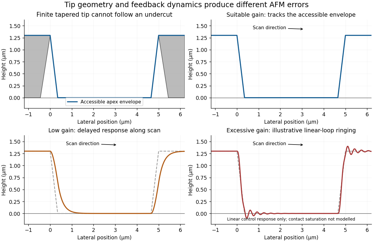
Illustrative AFM trace geometry and the effects of insufficient or excessive feedback gain
. Details. 
With gains too low for the scan speed, the vertical response lags the surface. On entering the depression during the left-to-right trace, the tip descends too slowly and the recorded edge rounds or extends into the trench. On climbing out, the tip can approach or contact the rising feature before the controller lifts it sufficiently, again distorting the edge. Thus the error depends on scan direction and can differ between trace and retrace. Slower scanning can reduce this bandwidth limitation, but it does not correct the geometrical inability to probe an overhang.
Excessive feedback gain can make the closed loop underdamped or unstable. Edge transitions then produce overshoot, ringing or oscillatory streaks in the recorded height. The apparent structure is a controller response rather than a real series of surface ridges. The exact amplitude and frequency depend on the actuator, cantilever, loop delay and controller settings; without those data one can sketch the qualitative ringing but cannot predict a unique quantitative trace.
In tapping-mode atomic force microscopy, the cantilever is driven near a resonance and its oscillation amplitude is monitored. Tip-surface interaction changes that amplitude. A controller compares it with a chosen setpoint and moves the vertical piezoelectric actuator to reduce the error. The recorded actuator displacement supplies the topography channel. A smaller amplitude during approach commonly triggers withdrawal and an increased amplitude during separation triggers approach, with the actual feedback sign set by the instrument's operating convention. Correct tracking requires enough response bandwidth without destabilizing the loop.
A conventional tapping tip tapers toward its apex, so its shank contacts an overhanging feature before its apex can probe underneath it. Critical-dimension atomic force microscopy instead uses a calibrated flared or laterally extended tip, with a relatively narrow neck and side-sensitive control. The lateral extension can contact a reentrant sidewall while the neck clears the upper edge. The measured profile still includes the tip's finite shape and must be interpreted with a tip calibration; changing the tip does not automatically eliminate all convolution errors.[ref]
Effects of Lateral Tip Control in CD-AFM Width Metrology by Ronald G. Dixson and others. Flared tips and bidirectional sidewall sensing
Lateral oscillation or dithering is added to the vertical oscillation. It provides a tip-sidewall interaction signal that can drive lateral feedback while the vertical channel maintains height control. This is how a suitable flared tip can track steep or reentrant walls. Treating the additional signal as merely a larger vertical tapping amplitude would not supply the required sidewall sensing.[ref]
Effects of Lateral Tip Control in CD-AFM Width Metrology by Ronald G. Dixson and others. Lateral-dither contribution to the effective tip envelope
An attached particle changes the effective tip shape, potentially creating a second contact apex. The image can then show duplicated or broadened copies of surface features, shifted edge positions and altered apparent roughness: a double-tip artefact or more general AFM tip-convolution artefact. Detachment can produce a sudden line-to-line change in that image kernel, so a region may abruptly recover a sharper profile. A change that follows the probe state or scan history should not be interpreted as a real reconstruction of the semiconductor surface.
Articles by others on the same topic
There are currently no matching articles.