In Fraunhofer diffraction, the phase difference from aperture coordinate y to observation angle theta is , with . Coherent superposition of the transmitted field elements therefore givesThe common propagation factor is omitted. This is the Fourier transform of the complex amplitude transmission, not of its intensity.
For a uniform slit of total width , integration gives , where . Its normalized intensity is , with a central maximum and first zeros at .
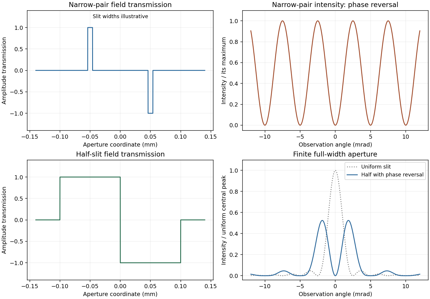
For a half-covered slit choose on the left half and on the right. Put and . The two equal rectangles have centres separated by h, soThis half-slit phase-step diffraction factorization is the phase-reversed two-slit interference factor multiplied by the diffraction envelope of each half-slit. Here the half-slit width and centre separation both equal the earlier0.1mm separation. The central intensity is zero; the largest off-axis pair satisfies , giving . Other zeros are at . The plot includes the requested uniform-slit and half-covered patterns.
Phase-step diffraction
. Complex field transmissions and their computed intensities; narrow rectangle widths are illustrative. Source. Details.
The slit transmissions have the same magnitude but opposite phase. An ideal narrow-slit representation isEquivalently draw two narrow rectangles at , one at+1 and the other at−1, and zero elsewhere. A finite rectangle width gives each slit its own diffraction envelope. The original aperture plot shows such rectangles with explicitly illustrative width; the negative value is a field phase reversal, not negative transmitted intensity.
For the narrow pair, the amplitude is . Hence phase-reversed double-slit diffraction givesThere is a central dark fringe. Minima obey , maxima , and the near-axis angular fringe period is . Finite slit widths multiply this interference profile by their single-slit envelope. The parent plot includes the narrow-pair profile.
Articles by others on the same topic
There are currently no matching articles.