For the series-fed parallel LC voltage response, use phasors with time dependence . The parallel branch has impedance , where . ThereforeAt the ideal parallel resonance its input impedance diverges. The input-current phase changes sign on crossing this pole; expressions there are interpreted by limits.
The capacitor voltage equals the parallel-branch voltage. Define . ThenAt low frequency ; at high frequency ; at resonance . Thus it is a band-pass voltage filter or resonant frequency selector. Its phase decreases continuously from through zero to . Half-power points satisfy and
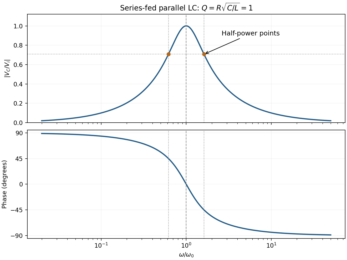

For the supplied component values and , and . The element peak currents areInductor and capacitor currents are opposite phasors; their magnitudes subtract here rather than add. The resistor carries the input current, withThese results assume ideal components and sinusoidal steady state.
Articles by others on the same topic
There are currently no matching articles.