Use five cascaded banks of 32 two-input multiplexers, for optional shifts of bits. The original circuit schematic below shows one bank per shift-amount bit; this is a left bit shift with zero fill, not a bit rotation.
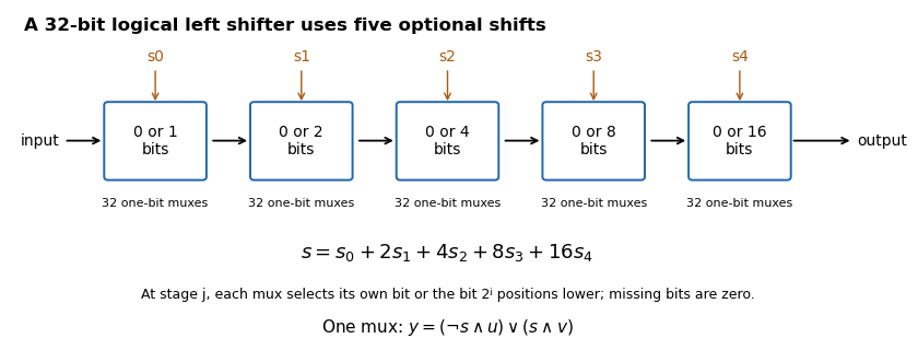

If , stage selects either its unchanged input or that input shifted left by . For bit position , the shifted candidate comes from position when it exists, and otherwise from zero. Composing the chosen stages shifts by the sum of their distances, so each amount from to is represented exactly by its five binary control bits. There are one-bit multiplexers, with five multiplexer delays along a bit path.
Articles by others on the same topic
There are currently no matching articles.