For a stationary rotating apparatus driven by a source with optical coherence and proper frequency , define . The source wave phase advances by between the emission times of the two contributions that meet at one readout spacetime event. Define the signed phase lag of the contribution and the corresponding displacement in units of one interference fringe byThe sign of a photographed spatial displacement also depends on the imposed fringe orientation; this definition fixes the theoretical sign through the delayed beam. In an equal-amplitude output, a representative light intensity is , where sets the chosen spatial interference fringe spacing . Moving by shifts the pattern by one fringe. A fixed output exactly at a bright or dark fringe has zero first-order intensity slope, so a known phase bias or a spatial fringe readout is useful for determining a small signed delay.
Choose a square of side , a rectangle by , and , with angular velocity parallel to the positive normal vectors. Both perimeters are , but the areas are and . Using , the leading predictions areThese are original model choices and predictions, not measured points. The square has times the response despite the equal path lengths. Reversing from to gives : the displacement magnitude between opposite rotations is twice the displacement magnitude from rest. Confusing these two comparisons introduces a factor-of-two error.
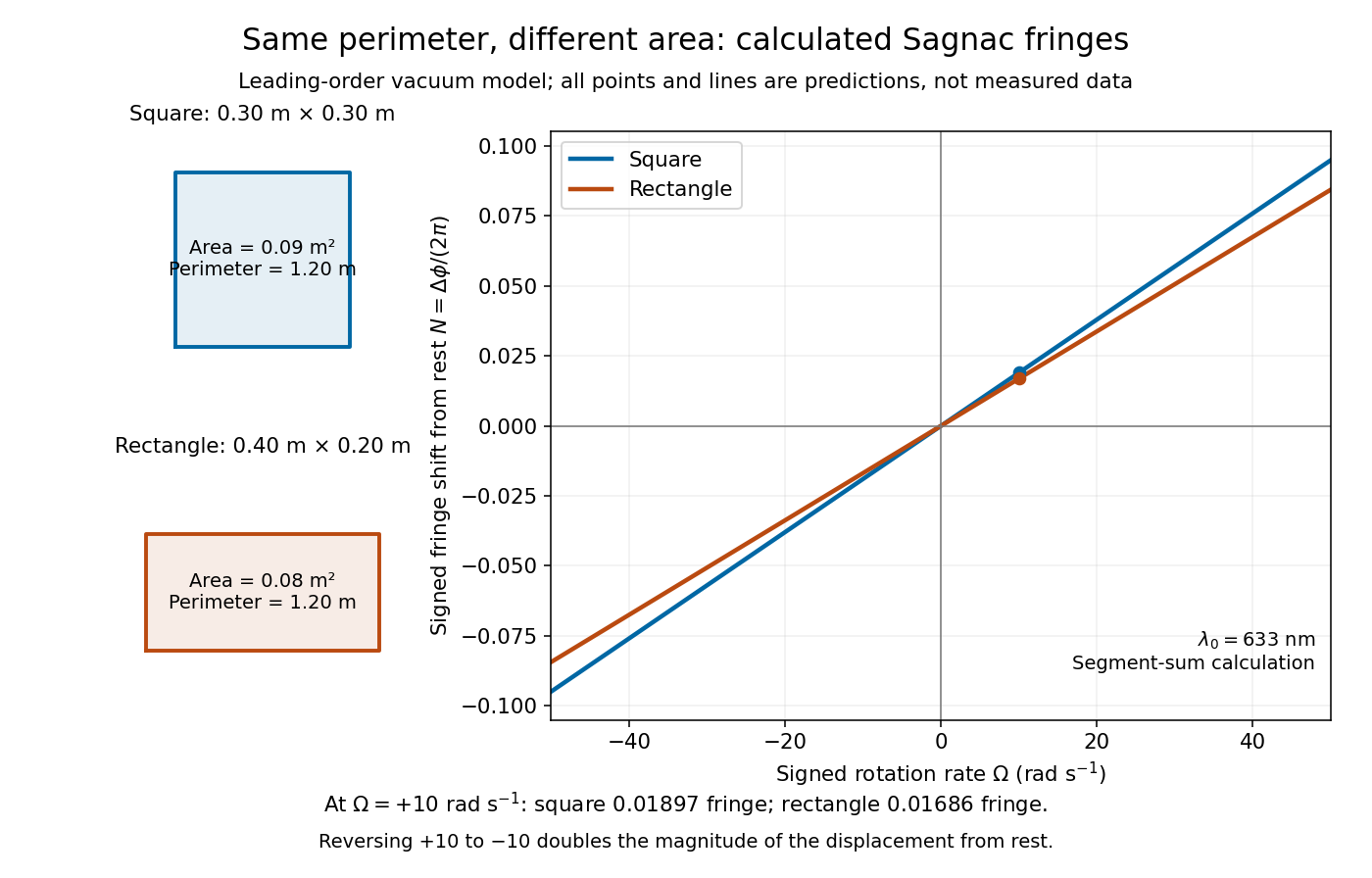
Independent path-segment calculation of the predicted fringe displacement for two equal-perimeter loops
. The generator sums along each straight segment, rather than inserting the enclosed area into the answer. Both loops are oriented counterclockwise. Lines and marked values are leading-order vacuum model predictions; no historical measurements are plotted. Details.
Articles by others on the same topic
There are currently no matching articles.