The Sagnac effect is a difference in return times, or an associated interference fringe displacement, for light sent in opposite directions around a closed optical path in a rotating apparatus. The light leaves one beam splitter, travels around the same loop in opposite senses, and returns to the rotating beam splitter and readout. For a slowly rotating apparatus in flat spacetime, the leading laboratory arrival-time difference isHere is the vacuum speed of light, is the apparatus's angular velocity relative to an inertial frame, and is the vector area oriented by the chosen positive direction around the closed curve . With positive rotation about the upward normal vector, the counterclockwise beam is labelled and arrives later. Reversing rotation, or reversing the orientation convention alone, changes the sign of .
The surprise is that a small loop can reveal its rotation by comparing two beams locally, even though each local vacuum speed of light measurement gives . A rotating reference frame is not a single inertial frame: a beam must catch the moving receiver after a full circuit. The Sagnac area law makes this difference a practical way to measure angular velocity, while the Relativistic Sagnac delay on a circular ring distinguishes laboratory coordinate time from the receiver's proper time.
A Sagnac interferometer uses a beam splitter to send light with optical coherence around a common closed optical path in opposite directions, then recombines the beams to read their phase difference. Mirrors or a guiding path define the loop; the source, beam splitter, loop and readout rotate together in the basic experiment. A small relative beam tilt makes spatial interference fringes whose displacement reveals a change of phase difference. At one fixed output, a photodetector can instead record the corresponding change in light intensity.
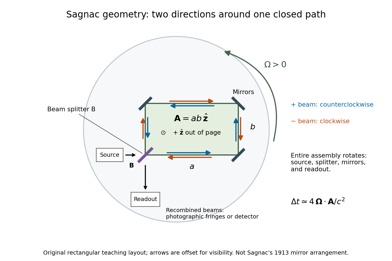
In 1913 Georges Sagnac mounted a lamp, collimator, beam splitter, four mirrors and photographic plate on a horizontal rotating platform. The mirrors defined a closed polygon; the two beams traversed it in opposite senses. A slight beam splitter adjustment produced visible interference fringes. A motor brought the platform to steady rotation, and switching the lamp exposed the plate. Comparing opposite senses of rotation revealed a reversing displacement. Changing the beam splitter adjustment supplied a further check against optical deformation. The report compared measured and calculated displacements. Georges Sagnac interpreted this as evidence for a luminiferous aether; the relativistic derivation below reproduces the delay without that hypothesis.[ref]
Regarding the Proof for the Existence of a Luminiferous Ether Using a Rotating Inteferometer Experiment by Georges Sagnac. Georges Sagnac, 1913 second report, inspected in William Lonc's 2008 English translation, pp. 77–80, §§1–3: rotating apparatus, photographic procedure, reversal and deformation controls, comparison table, historical interpretation
The readout measures a relative wave phase, not two stopwatch readings separated by an optical transit time. Reversal isolates a contribution odd in angular velocity: if a signed interference fringe position is to leading order, then cancels the fixed offset . Changes of alignment or temperature correlated with reversal can survive this subtraction. Thus the experimental inference concerns a reproducible rotating-loop phase difference, with controls for disturbances; it is not by itself a unique test of an underlying propagation hypothesis.
For a rigidly rotating prescribed vacuum path, use spatial coordinates attached to the apparatus and laboratory time . At a path point , the local apparatus velocity is . A light displacement has instantaneous laboratory displacement , up to the common rotation of the spatial axes. The null condition is thereforeWrite . To first order in , the positive root isReversing the path reverses the dot product term but leaves the leading path-length term unchanged. Subtract the two return times and use the scalar triple product identity:This is a line integral version of the Sagnac area law; the vector area identity also follows from Stokes theorem. For a mirror-defined polygon the actual ray paths move slightly as the mirrors rotate; the stationary optical path at zero rotation gives the same first-order result. The prescribed-path calculation is an idealization, not an exact finite-speed formula for every moving-mirror layout.
The dot product explains the geometry: only the projection of the oriented vector area along the angular velocity contributes. A planar loop whose normal vector is perpendicular to has zero leading delay. For repeated traversals with the same orientation, the signed vector areas add; oppositely oriented lobes can cancel even when the total unsigned area is large. Equal perimeter alone does not imply equal response. A constant translational velocity contributes nothing to this leading closed-path line integral, since .
For a stationary rotating apparatus driven by a source with optical coherence and proper frequency , define . The source wave phase advances by between the emission times of the two contributions that meet at one readout spacetime event. Define the signed phase lag of the contribution and the corresponding displacement in units of one interference fringe byThe sign of a photographed spatial displacement also depends on the imposed fringe orientation; this definition fixes the theoretical sign through the delayed beam. In an equal-amplitude output, a representative light intensity is , where sets the chosen spatial interference fringe spacing . Moving by shifts the pattern by one fringe. A fixed output exactly at a bright or dark fringe has zero first-order intensity slope, so a known phase bias or a spatial fringe readout is useful for determining a small signed delay.
Choose a square of side , a rectangle by , and , with angular velocity parallel to the positive normal vectors. Both perimeters are , but the areas are and . Using , the leading predictions areThese are original model choices and predictions, not measured points. The square has times the response despite the equal path lengths. Reversing from to gives : the displacement magnitude between opposite rotations is twice the displacement magnitude from rest. Confusing these two comparisons introduces a factor-of-two error.
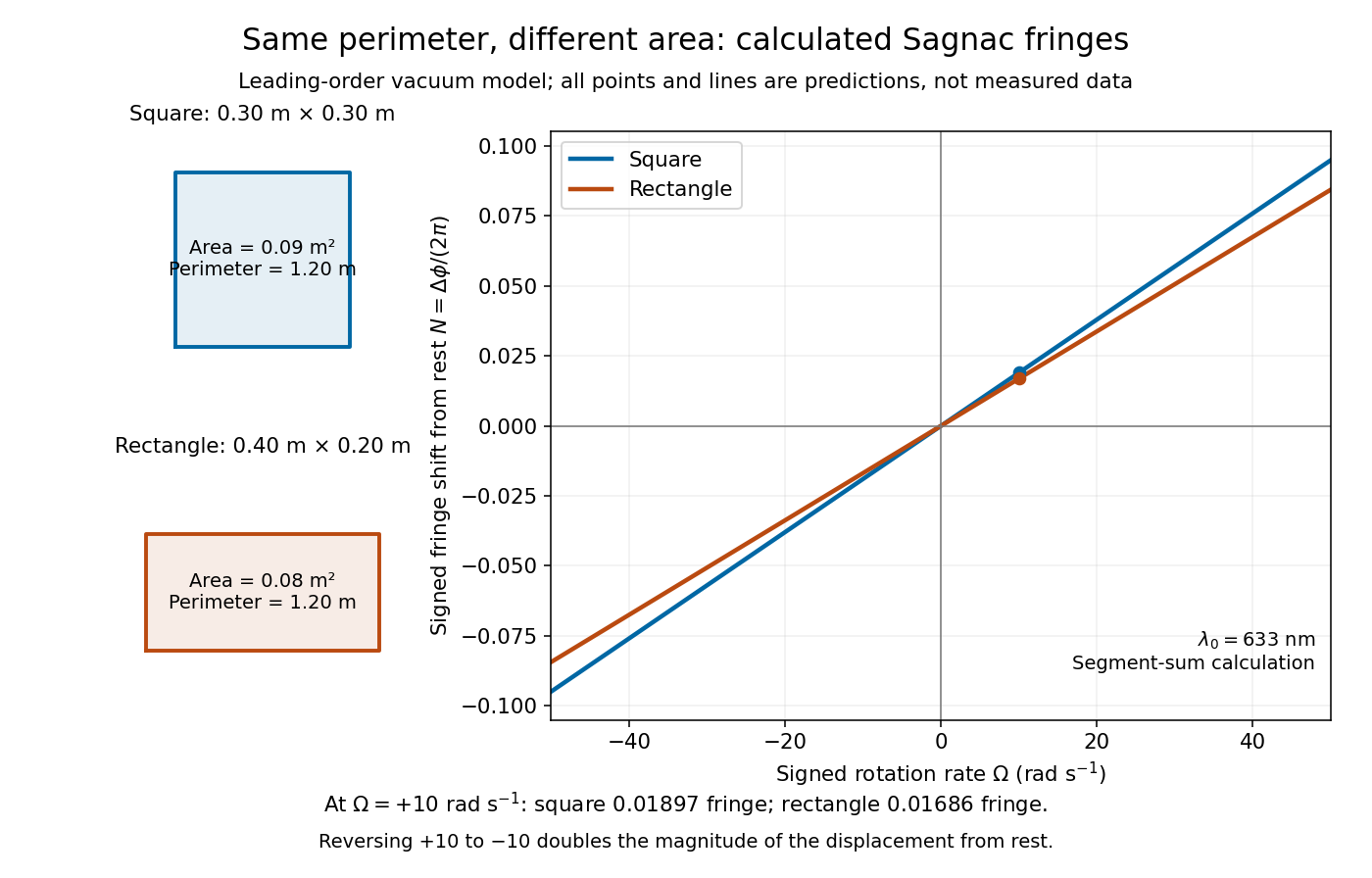
Independent path-segment calculation of the predicted fringe displacement for two equal-perimeter loops
. The generator sums along each straight segment, rather than inserting the enclosed area into the answer. Both loops are oriented counterclockwise. Lines and marked values are leading-order vacuum model predictions; no historical measurements are plotted. Details.Consider an ideal circular vacuum path of laboratory radius , a limit of closely spaced mirrors constraining light around the circle at laboratory speed . The source and detector rotate uniformly together with signed angular velocity , where , in flat spacetime. Let be the laboratory circumference and the positive area. The pulse travels counterclockwise and the pulse clockwise, independently of the sign of . Both depart from the detector at .
Unwrap the circle into a laboratory arc coordinate. The two first-return conditions areConsequently the exact laboratory arrival times and their difference areThe denominators are closing rates in these laboratory equations; they are not local speed of light measurements by a rotating observer. The two arrival spacetime events lie on the same detector world line. Its constant speed is , so proper time along that world line givesThus laboratory coordinate-time and rotating-detector proper time delays agree only to leading order at small . The radius and circumference here are laboratory quantities, not lengths obtained by laying comoving rods around the rim. Finite mirror polygons, transparent media, and optical dispersion require their own path and propagation assumptions before using an exact formula.
An exact dimensionless check takes . Relative to , the laboratory arrival times are and , giving . The detector instead records . The leading Sagnac area law would give . These are model values chosen to make the relativistic distinction visible, not attainable parameters of the historical apparatus.
The rotating loop does not constitute a universal measurement of the one-way speed of light. It compares completed circuits at a single readout; assigning a velocity to each remote leg additionally requires a clock synchronization convention. Local Einstein synchronisation around a rotating rim does not close into a single globally synchronized clock network: the accumulated mismatch is another expression of the rotating-path asymmetry. Local comoving vacuum measurements still give in both directions. Special relativity predicts a nonzero closed-loop delay because the receiver moves during propagation, while no single comoving inertial frame covers the whole circuit.
Articles by others on the same topic



The Sagnac effect is a phenomenon observed in rotating reference frames and is particularly significant in the study of relativistic physics. It was first demonstrated by French physicist Georges Sagnac in 1913. The effect occurs when a beam of light is split into two beams that travel in opposite directions around a closed path, such as a loop. If the path is rotating relative to an inertial observer, the two beams will take different amounts of time to complete the circuit.