A transverse optical cavity mode is a resonant field pattern across the direction of propagation in an optical cavity. After propagation and reflection through a round trip, the mode reproduces its transverse shape up to a complex amplitude factor. Longitudinal order counts axial phase cycles; transverse order describes the pattern across the beam. Different transverse patterns can resonate at the same frequency, as in confocal transverse-mode degeneracy.
In an ideal paraxial cavity with suitable spherical mirrors, a Cartesian Hermite-Gaussian optical mode at its waist has field proportional towhere are Hermite polynomials, are nonnegative integers, and is the beam waist radius. The intensity is proportional to , not to the signed field. The primary photonics notes give these transverse solutions, their phase advance and lower-order patterns.[ref]
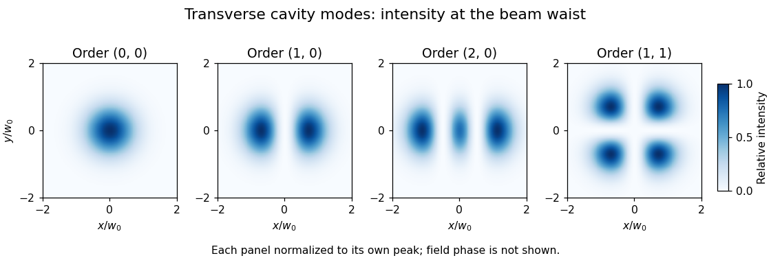
For , the intensity is a single Gaussian beam spot. For , , so intensity is proportional to . It vanishes on and its two maxima occur at , . The two lobes have opposite field signs even though both have positive intensity. The pattern has two crossing nodal lines and four intensity lobes.

For an ideal empty two-mirror cavity of length , set . On the near-planar stable branch with , the resonance frequencies areThe transverse contribution is a Gouy phase correction to the round-trip phase. Other branches require a consistent phase choice; the square root alone should not erase that choice. For an original example, and give and a one-order transverse spacing at fixed . Modes with the same are degenerate in this ideal symmetric model.
A proposed observation scans cavity length while recording both transmission peaks and a camera image of the transmitted beam. Translating or tilting the incident beam changes its overlap with different transverse modes; matching the incident wavefront and width favors the fundamental mode. A transmission peak alone cannot identify the spatial pattern, and an intensity image alone does not recover its phase. Finite apertures, astigmatism and mirror imperfections alter losses and split ideal degeneracies; state the cavity geometry and imaging plane when comparing observations.
A Hermite-Gaussian optical mode is a separable paraxial field pattern whose transverse dependence is a product of Hermite polynomials and a Gaussian beam envelope. In an ideal aligned optical resonator with suitable spherical mirrors, these patterns form a family of transverse optical cavity modes. The two nonnegative integer orders count the straight nodal lines along the chosen transverse axes. The primary photonics notes give the mode fields and their order-dependent phase advance.[ref]
At a common waist plane, choose a unit-normalized scalar fieldHere uses the physicists' Hermite polynomial convention, with , and . The normalization follows fromAfter the two coordinate substitutions, . Thus coefficients in a common-plane expansion can be recovered by inner products; the modes are orthogonal field patterns, not independent bright spots.
For , intensity is proportional to , so its maxima lie at , . At , the bright lobes are about apart. The field changes sign across , although an intensity camera records positive intensity on both sides. For , the nodal lines instead lie at . These patterns are illustrated in transverse optical cavity mode using individually peak-normalized images; equal peak intensity is different from equal integrated power.
A second-moment width of a Hermite-Gaussian optical mode distinguishes these multi-lobed beams quantitatively. Applying the Hermite polynomial recurrence inside the normalized integrals givesFor order , the RMS widths are horizontally and vertically, despite the same envelope parameter . Reporting a fitted single-lobe radius without its definition can obscure this difference.
During propagation the beam radius and wavefront curvature evolve, and the Gouy phase is multiplied by . Consequently, transverse order contributes to the resonator's frequency condition and to confocal transverse-mode degeneracy. A proposed experiment scans the resonator while imaging a specified plane, then interferes its output with a reference field to test the phase reversal across a node. An intensity fit alone does not establish a pure coherent mode: mixtures, astigmatism, finite apertures and degeneracy can alter what is observed.
Articles by others on the same topic
There are currently no matching articles.