Topics (203k) Articles (205k) Users (298) Discussions (237) Comments (383) Files (715) New article

Design computing refers to the intersection of design principles and computational methods. It encompasses the use of computational tools, algorithms, and digital technologies in the design process across various disciplines, such as architecture, industrial design, graphic design, and engineering. Design computing integrates traditional design methods with advanced computing techniques to enhance creativity, efficiency, and innovation.
Constructive Solid Geometry (CSG) is a modeling technique used in computer graphics and computer-aided design (CAD) to create complex 3D shapes by combining simpler primitive shapes through Boolean operations. The fundamental primitive shapes typically used in CSG include basic geometric forms like cubes, spheres, cylinders, cones, and more.
In computer-aided design (CAD), a constraint is a rule or limitation applied to the elements of a design model, which defines their relationships and interactions. Constraints help maintain the integrity and functionality of a design by ensuring that certain conditions are met, regardless of changes made to the model. There are different types of constraints commonly used in CAD: 1. **Geometric Constraints**: These define the spatial relationships between geometric entities.
Computer-automated design, often referred to as computer-aided design (CAD), is the use of computer software and tools to create, modify, analyze, and optimize designs. CAD is widely used in various fields such as architecture, engineering, product design, and manufacturing. It allows designers and engineers to produce precise drawings and models, which can be easily altered and shared.
Computer-aided production engineering (CAPE) refers to the use of computer software and technology to assist in the planning, design, analysis, and optimization of production processes and systems. CAPE integrates various engineering disciplines to improve productivity, quality, and efficiency in manufacturing operations. It encompasses several key areas: 1. **Production Planning and Scheduling**: Using algorithms and software to optimize manufacturing schedules, inventory management, and resource allocation to meet production targets efficiently.
Computer-aided inspection (CAI) refers to the use of computer technology and software tools to assist in the inspection and quality control processes of manufactured goods, components, and systems. The primary goal of CAI is to improve the accuracy, efficiency, and consistency of inspections, leading to better quality assurance and reduced production costs.
Computer-aided industrial design (CAID) refers to the use of computer software and systems to assist in the design, development, and production of industrial products. This approach leverages advanced tools and technologies to streamline the design process, enhance creativity, and improve the quality of the final product. Key components of CAID include: 1. **3D Modeling**: Designers use software to create three-dimensional models of products, allowing them to visualize and manipulate designs in a virtual space.
Computer-Aided Design (CAD), Computer-Aided Manufacturing (CAM), and Computer-Aided Engineering (CAE) are integral parts of design and manufacturing processes in various industries. Each of these areas employs specialized file types and viewers to manage and visualize the data associated with designs, simulations, and manufacturing processes.
Collaborative product development (CPD) is a process in which multiple stakeholders—including designers, engineers, manufacturers, marketers, and sometimes customers—work together to create a product from conception through to market launch. This approach emphasizes teamwork and communication across different disciplines to enhance innovation, improve product quality, and reduce time-to-market.
In the context of design and manufacturing, particularly in industries such as automotive and aerospace, a "Class A surface" refers to a high-quality surface finish that is characterized by its aesthetic appearance and smoothness. These surfaces are typically visible and often have demanding visual requirements. Class A surfaces are essential for parts that are exposed to public view or that have strict aesthetic criteria, such as the outer body panels of vehicles.
Cadwork is a software application primarily used for computer-aided design (CAD) and building information modeling (BIM) in the fields of timber construction, architecture, and wood engineering. It provides a comprehensive solution for designing, modeling, and planning complex structures, especially those that involve timber materials. Cadwork is known for its user-friendly interface and advanced tools that allow users to create detailed 3D models, generate technical drawings, produce cutting lists, and manage project workflows.
COBie, or Construction Operations Building Information Exchange, is a standardized data model used in the construction and facilities management industries. It provides a structured format for capturing and sharing information about buildings and infrastructure projects, particularly focusing on the information needed for the operation and maintenance of facilities. The main objectives of COBie are to streamline the process of information transfer from the construction phase to the operational phase, improve the quality of data related to the building, and facilitate better management of facilities throughout their lifecycle.
CAD data exchange refers to the process of sharing and transferring computer-aided design (CAD) data between different software applications or systems. This is crucial in industries such as engineering, architecture, manufacturing, and construction, where various stakeholders need to collaborate and share design information efficiently. Key aspects of CAD data exchange include: 1. **File Formats**: Various CAD software applications use different file formats (e.g., DWG, DXF, STEP, IGES, STL).
CAD/CAM in the footwear industry refers to the use of Computer-Aided Design (CAD) and Computer-Aided Manufacturing (CAM) technologies to design and manufacture footwear. These technologies streamline the production process, enhance design precision, and improve overall efficiency. ### CAD (Computer-Aided Design) - **Design Creation**: CAD software allows designers to create detailed 2D and 3D models of footwear. This includes everything from the shoe's silhouette to intricate design elements like patterns and textures.
CAD/CAM dentistry refers to the use of Computer-Aided Design (CAD) and Computer-Aided Manufacturing (CAM) technologies in the planning and creation of dental restorations. This innovative approach has transformed traditional dental practices by allowing for more precise, efficient, and aesthetic outcomes. Here’s a breakdown of the two components: 1. **CAD (Computer-Aided Design)**: This aspect involves using software to design dental restorations digitally.
CAD/CAM stands for Computer-Aided Design and Computer-Aided Manufacturing. These two technologies are often used together in various industries, especially in manufacturing, engineering, architecture, and design. ### CAD (Computer-Aided Design) CAD refers to the use of software to create precise drawings, models, and specifications for various types of projects. It allows designers and engineers to: - Create detailed 2D or 3D representations of a product or structure.
C3D Toolkit is a software library and framework designed for working with 3D science data, particularly in the field of computational mechanics and finite element analysis (FEA). It is often utilized for mesh-based simulations, enabling users to read, manipulate, and write data with a focus on a variety of file formats and datasets typically used in engineering and scientific research.
Building Lifecycle Management (BLM) is a holistic approach to managing the entire lifecycle of a building or infrastructure project, from conception and design through construction and operation to eventual decommissioning or renovation. BLM integrates various disciplines and technologies, such as building information modeling (BIM), project management, and facility management, to optimize building performance, enhance sustainability, and improve overall project outcomes.
Building Information Modeling (BIM) is a digital representation of the physical and functional characteristics of a facility. It is a collaborative process that involves the generation and management of digital representations of a project's physical and functional characteristics. BIM serves as a shared knowledge resource, which is used to create a reliable basis for decisions during the project lifecycle, from initial design through construction, operation, and maintenance. **Key aspects of BIM include:** 1.
Boundary representation, often abbreviated as B-rep, is a method used in computer graphics and geometric modeling to represent the shape and topology of a three-dimensional object. In B-rep, the object is defined by its boundaries, which include faces, edges, and vertices. Here are the key components of B-rep: 1. **Vertices**: The corner points of the object where edges meet. 2. **Edges**: The line segments that connect vertices.
Pinned article: Introduction to the OurBigBook Project
Welcome to the OurBigBook Project! Our goal is to create the perfect publishing platform for STEM subjects, and get university-level students to write the best free STEM tutorials ever.
Everyone is welcome to create an account and play with the site: ourbigbook.com/go/register. We belive that students themselves can write amazing tutorials, but teachers are welcome too. You can write about anything you want, it doesn't have to be STEM or even educational. Silly test content is very welcome and you won't be penalized in any way. Just keep it legal!
Intro to OurBigBook
. Source. We have two killer features:
- topics: topics group articles by different users with the same title, e.g. here is the topic for the "Fundamental Theorem of Calculus" ourbigbook.com/go/topic/fundamental-theorem-of-calculusArticles of different users are sorted by upvote within each article page. This feature is a bit like:
- a Wikipedia where each user can have their own version of each article
- a Q&A website like Stack Overflow, where multiple people can give their views on a given topic, and the best ones are sorted by upvote. Except you don't need to wait for someone to ask first, and any topic goes, no matter how narrow or broad
This feature makes it possible for readers to find better explanations of any topic created by other writers. And it allows writers to create an explanation in a place that readers might actually find it.
Figure 1. Screenshot of the "Derivative" topic page. View it live at: ourbigbook.com/go/topic/derivativeVideo 2. OurBigBook Web topics demo. Source. - local editing: you can store all your personal knowledge base content locally in a plaintext markup format that can be edited locally and published either:This way you can be sure that even if OurBigBook.com were to go down one day (which we have no plans to do as it is quite cheap to host!), your content will still be perfectly readable as a static site.
- to OurBigBook.com to get awesome multi-user features like topics and likes
- as HTML files to a static website, which you can host yourself for free on many external providers like GitHub Pages, and remain in full control
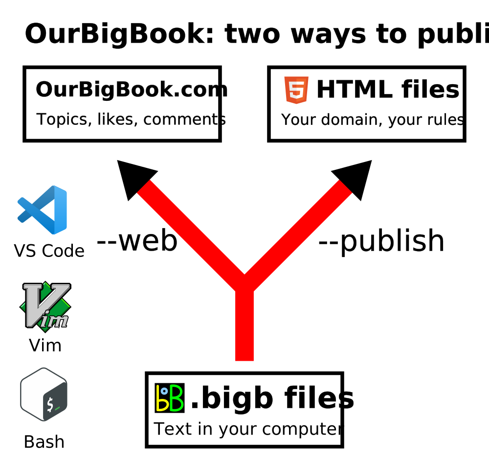
Figure 2. You can publish local OurBigBook lightweight markup files to either OurBigBook.com or as a static website.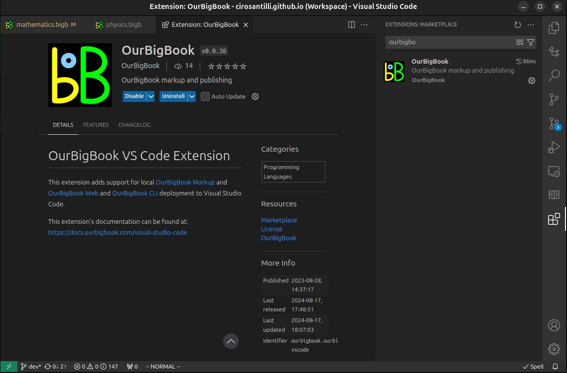
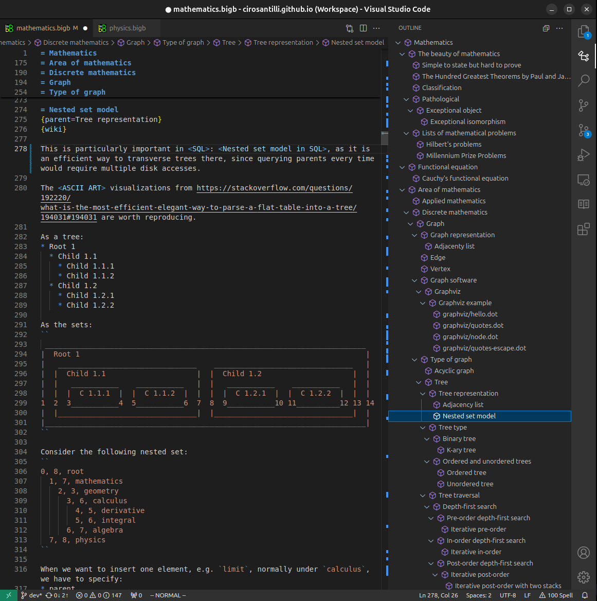
Figure 3. Visual Studio Code extension installation.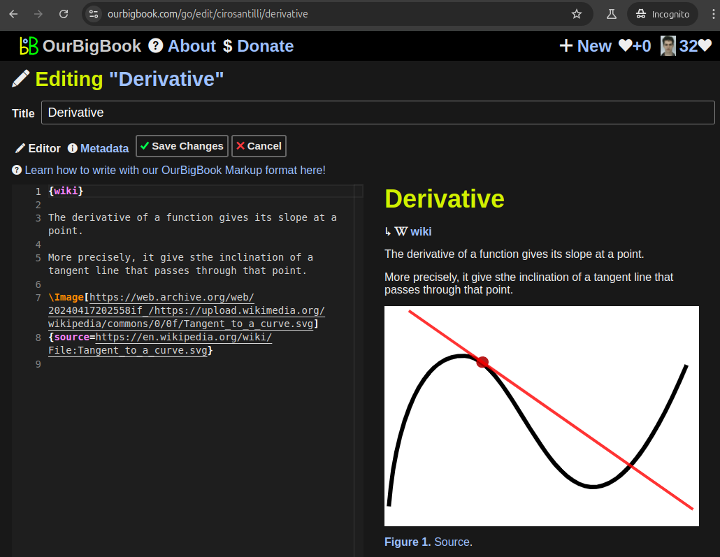
Figure 5. . You can also edit articles on the Web editor without installing anything locally. Video 3. Edit locally and publish demo. Source. This shows editing OurBigBook Markup and publishing it using the Visual Studio Code extension. 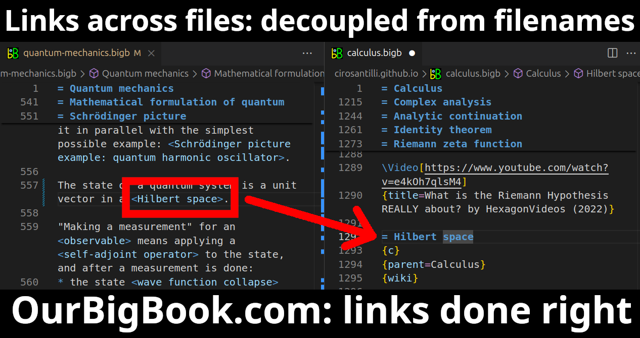
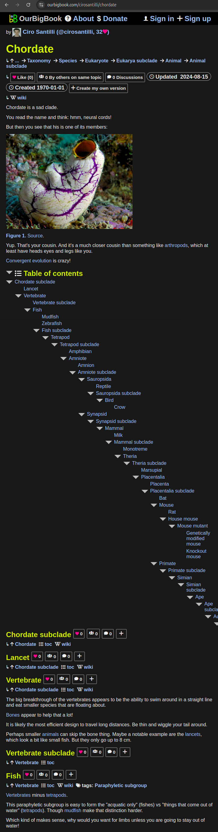
- Infinitely deep tables of contents:
All our software is open source and hosted at: github.com/ourbigbook/ourbigbook
Further documentation can be found at: docs.ourbigbook.com
Feel free to reach our to us for any help or suggestions: docs.ourbigbook.com/#contact