Conjugate pinholes in confocal microscopy
ID: conjugate-pinholes-in-confocal-microscopy

Two planes are optically conjugate when an optical lens system images one onto the other. In confocal microscopy, an illumination pinhole is imaged onto the selected specimen point, and that specimen point is imaged onto the detection pinhole. Thus the two apertures select corresponding positions in different planes; they need not occupy the same physical plane. Modern laser instruments can supply the illumination point with an optical fiber or a suitable focused laser mode instead of a separate metal illumination pinhole. [ref]
Confocal microscopy (chapter manuscript) by Brad Amos and others. Amos, McConnell and Wilson, Confocal microscopy, manuscript pp. 5, 7–8: conjugate foci, Fig. 3, fiber-delivered illumination
A fluorescent emitter at the selected optical focus forms a compact point spread function at the detection aperture. An emitter displaced axially produces a broadened spot there through defocus; a smaller fraction of its collected light passes. The emitter still exists and still emits photons. Rejected photons strike the opaque mask or other parts of the instrument instead of contributing to the accepted detector channel. Neither a finite pinhole nor diffraction makes the accepted out-of-focus contribution exactly zero.
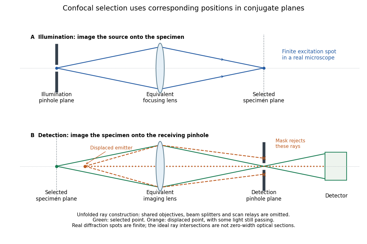
Conjugate illumination and detection pinholes in confocal microscopy
. Original unfolded geometrical optics schematic, not a scale drawing of an instrument. The top panel images an illumination pinhole onto the specimen; the lower panel images the selected specimen point onto the detection pinhole. Dashed orange light rays from an axially displaced point strike the mask, while an axial orange light ray passes. Real spots have finite point spread functions through diffraction; the drawing's perfect green intersection is only a ray construction. A fluorescence instrument may fold both paths through the same objective optical lens using a wavelength-selective beam splitter. Details.
New to topics? Read the docs here!